System, method and apparatus for thermal energy management in a roof

a technology of thermal energy management and roof, applied in ventilation systems, lighting and heating apparatus, heating types, etc., can solve the problems of low cooling energy cost, heating penalties, and not designed for managing solar heat during night time or changing seasons

Active Publication Date: 2015-03-26
CERTAINTEED CORP
View PDF47 Cites 24 Cited by
  • Summary
  • Abstract
  • Description
  • Claims
  • Application Information

AI Technical Summary

Problems solved by technology

Although such products lower cooling energy costs, particularly in the “sunbelt” states, they are not designed for managing solar heat during night time or changing seasons.
In colder climates, such products can have heating penalties due to the loss of solar heat.
This is also true for the use of radiant barriers to reduce solar heat flux into the attic, which are not designed to capture the solar heat and manage it in order to maximize the energy efficiency.
Again, such systems are not designed for taking the advantage of solar heat and storing them for later use during the heating period.
However, the cost effectiveness of such systems has not been confirmed or validated.

Method used


Image

  • System, method and apparatus for thermal energy management in a roof
  • System, method and apparatus for thermal energy management in a roof
  • System, method and apparatus for thermal energy management in a roof

Examples


Embodiment Construction

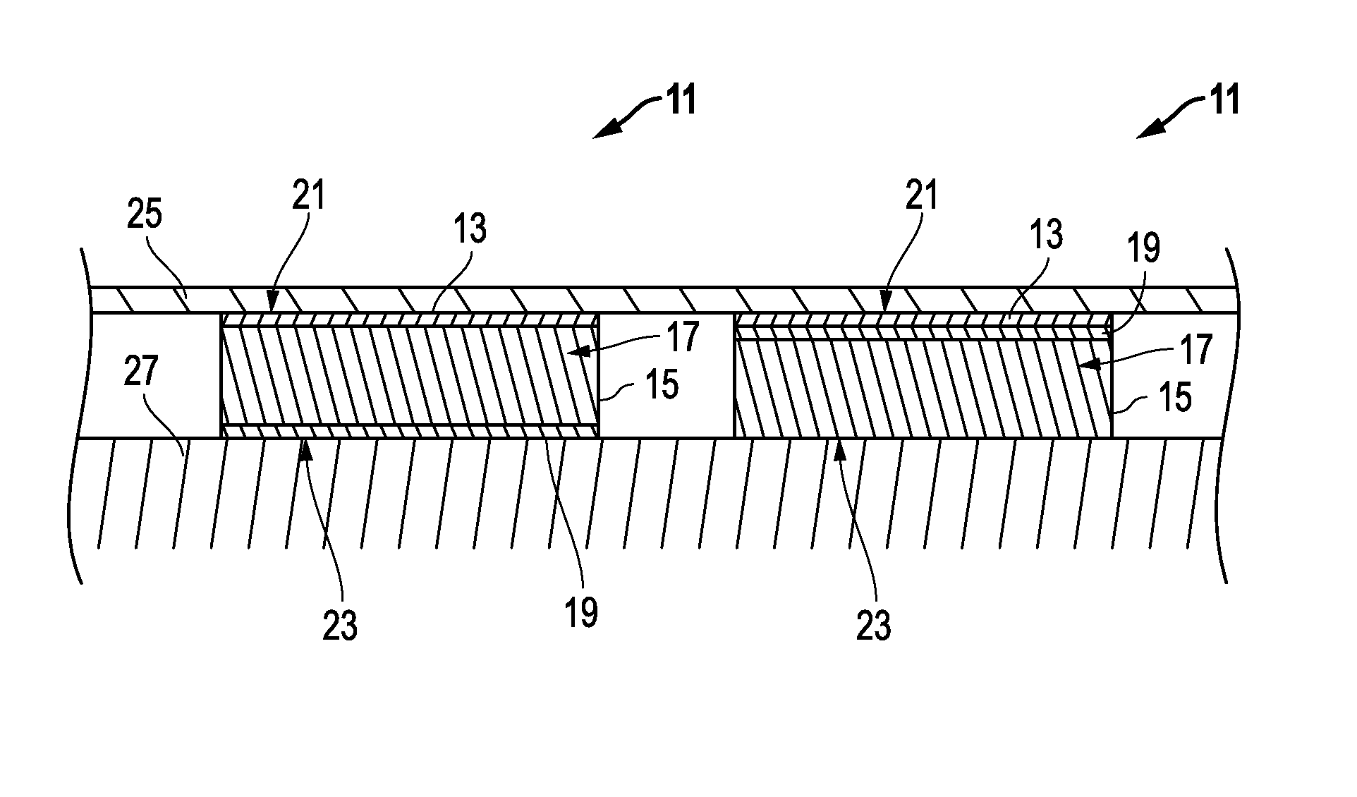
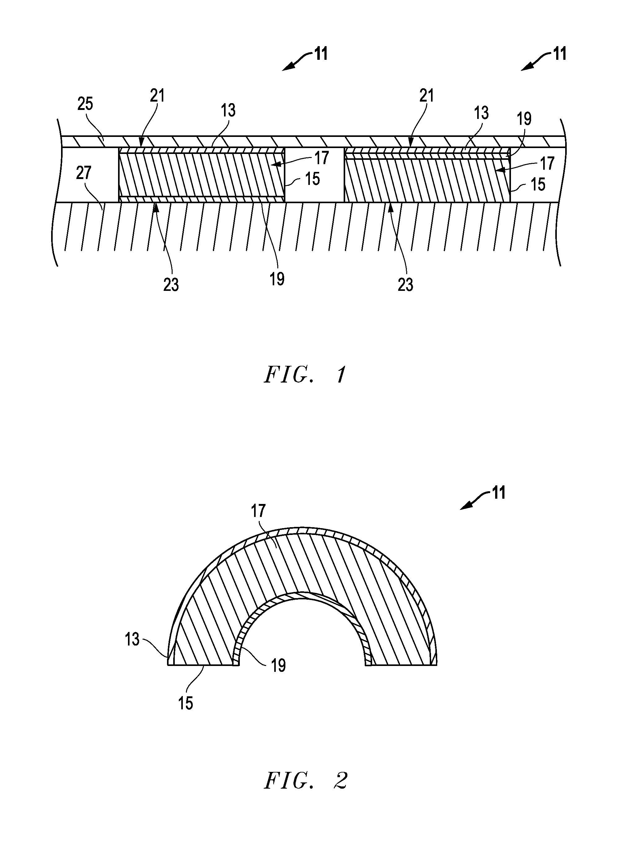
[0022]Embodiments of a building product may include applications such as roofing, siding and other building application. Versions of the roofing may include a roof composite, roof product, roof shingle, roof tile, or a stand-alone layer or an underlayment layer.

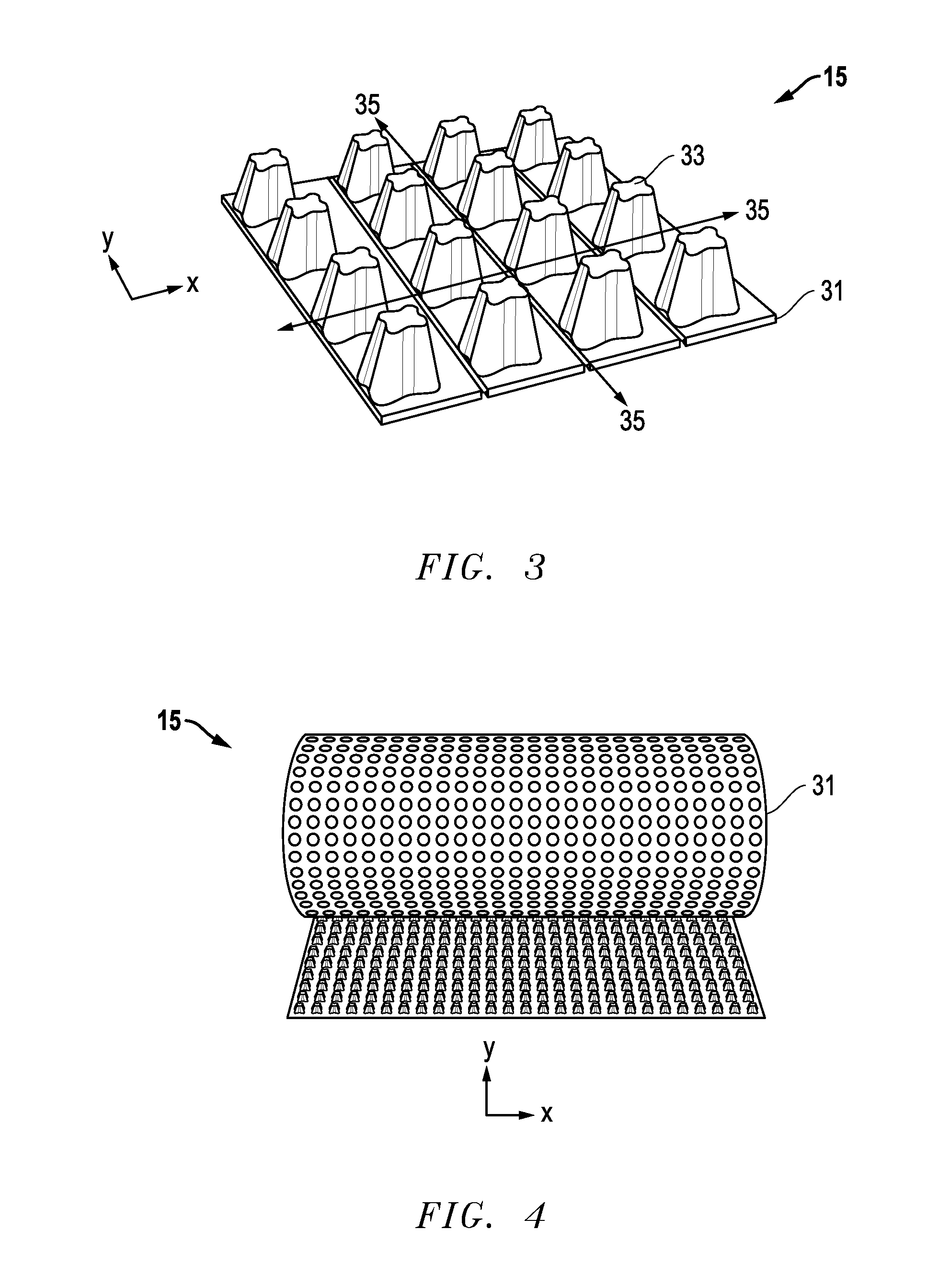
[0023]In one example (FIG. 1), a building product 11 can include a top layer 13. The top layer 13 can be substantially rigid such that it is configured to be walkable. The building product 11 also may include a radiant barrier layer 19 that is configured to reflect heat. The building product 11 may further comprise a vent layer 15. Embodiments of the radiant barrier layer 19 can face the vent layer 15, and can be above or below it. Thus, vent layer 15 can be located between the top layer 13 and the radiant barrier layer 19. In another embodiment, the radiant barrier layer 19 may be located between the top layer 13 and the vent layer 15. In some applications, radiant barriers may be more effective at blocking radiant heat when...


PUM

PropertyMeasurementUnit
thicknessaaaaaaaaaa
thicknessaaaaaaaaaa
thicknessaaaaaaaaaa

Abstract

A building product may include a top layer that is substantially rigid such that it is configured to be walkable. In addition, the building product may include a radiant barrier layer configured to reflect heat, and a vent layer located between the top layer and a roof deck. The vent layer may comprise air flow channels configured to transfer heat through at least a portion of the roof product. The top layer, vent layer and radiant barrier layer can form a unitary structure.

Description

[0001]This application claims priority to and the benefit of U.S. Provisional Application No. 61 / 881,731, filed Sep. 24, 2013, which is incorporated herein by reference in its entirety.BACKGROUND OF THE INVENTION[0002]1. Field of the Disclosure[0003]The present invention relates in general to roofing and, in particular, to a system, method and apparatus for thermal energy management in a roof.[0004]2. Description of the Related Art[0005]Typical residential roofs in the North America have bitumen-based roofing materials that provide satisfactory water shedding, long term durability and have aesthetic appeal. Most asphaltic roofing materials are colored in traditional dark earth tones. These colors absorb significant amounts of solar heat during hot summer times, which penetrates through the roof deck, attic and ceiling into the house. The heat penetration increases the need for cooling energy for the indoor comfort of residence occupants.[0006]It would be advantageous to have a roofi...

Claims


Application Information

Patent Timeline
Patent Type & Authority Applications(United States)
IPC IPC(8): E04D1/30E04D13/12E04D13/17E04D13/00
CPCE04D1/30E04D13/00E04D2001/309E04D13/172E04D13/12E04D5/12Y10T29/49623Y10T428/239Y10T428/24281
Inventor KALKANOGLU, HUSNU M.SHIAO, MING LIANGJACOBS, GREGORY F.RANJAN, RAJESH
Owner CERTAINTEED CORP
Why Eureka
Try Eureka