Low temperature cooling and dehumidification device with reversing airflow defrost for dehumidification and water generation applications where cooling coil inlet air is above freezing

a technology of defrosting device and airflow, which is applied in the direction of defrosting, heating type, domestic cooling apparatus, etc., can solve the problems of mechanical cooling and dehumidification system, restricting airflow, and accumulating frost, so as to avoid air restriction

Active Publication Date: 2015-03-26
KENTUCKIANA CURB
View PDF5 Cites 5 Cited by
  • Summary
  • Abstract
  • Description
  • Claims
  • Application Information

AI Technical Summary

Benefits of technology

[0010]Therefore a device is provided for cooling and dehumidifying an air stream to temperatures at or below freezing, while avoiding air restriction due to frost buildup in one or more one cooling coils, where cooling coil inlet air is above freezing. The device includes at least two opposing inlet air dampers at the device air inlet and at least two opposing outlet air dampers at the device air outlet.
[0011]The device further includes two airflow circuits, where at least one inlet damper is in airflow communication with at least one outlet damper, through at least one cooling coil and by alternating the dampers in each of two airflow circuits, so that reversal of airflow occurs through said the one or more cooling coils, routing warmer inlet air to the previously cold outlet of the one or more cooling coils, while maintaining airflow in one direction through said device.
[0012]Optionally the device can include one or more air-to-air heat exchangers for exchanging energy between the colder air leaving the one or more cooling coils and the relatively warmer air entering the one or more one cooling coils in each of the aforementioned airflow circuits.
[0013]In general, the present invention limits frost formation in a low temperature cooling and dehumidification system by passing ambient air through a containment in which there is a cooling coil array comprising a coil through which flows a coolant for cooling and dehumidifying the ambient air whereby a condensate is formed on an outside surface of the coil, where condensate freezes to form a frost formation where the coldest air meets the coldest portion of the coil. The ambient air makes a first pass through an air-to-air heat exchanger located within the containment located above the coil array and a second pass through the heat exchanger after leaving the coil array. The frost thus formed on the coil is periodically removed by reversing direction of air flow through the containment, whereby the reversal of air flow recurs without interrupting cooling and dehumidification or changing direction of flow into and out of the containment. The water condensate generated and formed is collected in a plenum under the array within the containment.
[0014]Any of the dehumidification configurations of this invention produce condensate as a byproduct of normal operation. This generated condensate can be collected in lieu of being drained to a sewer. In some venues, this may be considered a useful commodity commonly called grey water. It can be used as is for plant irrigation, waste flushing, outdoor ground washing, etc. By providing the proper piping and a storage tank, these dehumidification systems can be a reliable source of grey water. If the water thus generated and collected meets drinking water standards, it can be used as potable water if the grey water produced is optionally further treated if required after testing, it can also be used as a ready supply of potable water.

Problems solved by technology

Mechanical cooling and dehumidification systems are generally restricted to delivering air temperatures safely above freezing to avoid complications associated with frost buildup in the cooling coil and subsequent air restriction.
Frost accumulates over time and eventually restricts airflow, requiring some means for defrosting.
This introduction of heat to a cooling process interrupts operation and is inefficient, resulting in an increase in overall energy consumption.

Method used


Image

  • Low temperature cooling and dehumidification device with reversing airflow defrost for dehumidification and water generation applications where cooling coil inlet air is above freezing
  • Low temperature cooling and dehumidification device with reversing airflow defrost for dehumidification and water generation applications where cooling coil inlet air is above freezing
  • Low temperature cooling and dehumidification device with reversing airflow defrost for dehumidification and water generation applications where cooling coil inlet air is above freezing

Examples


Embodiment Construction

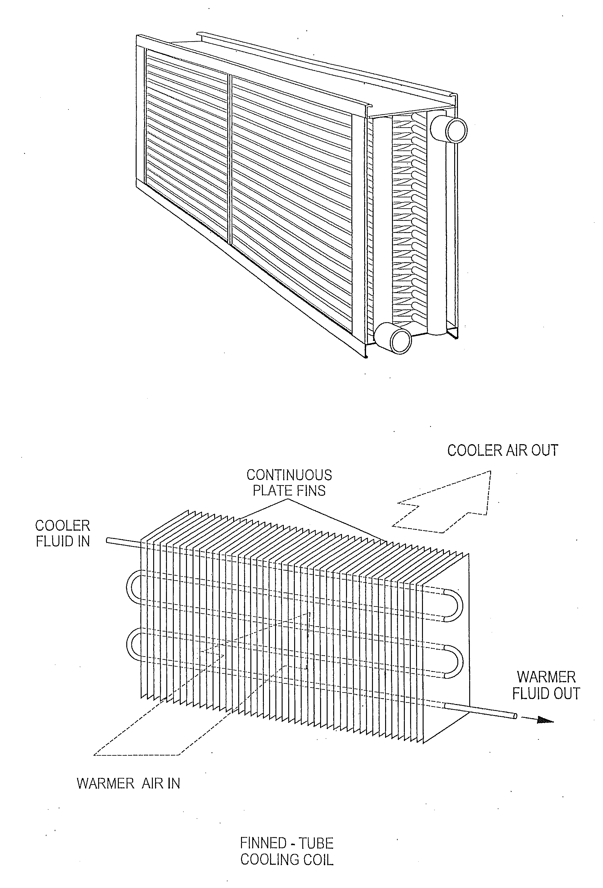
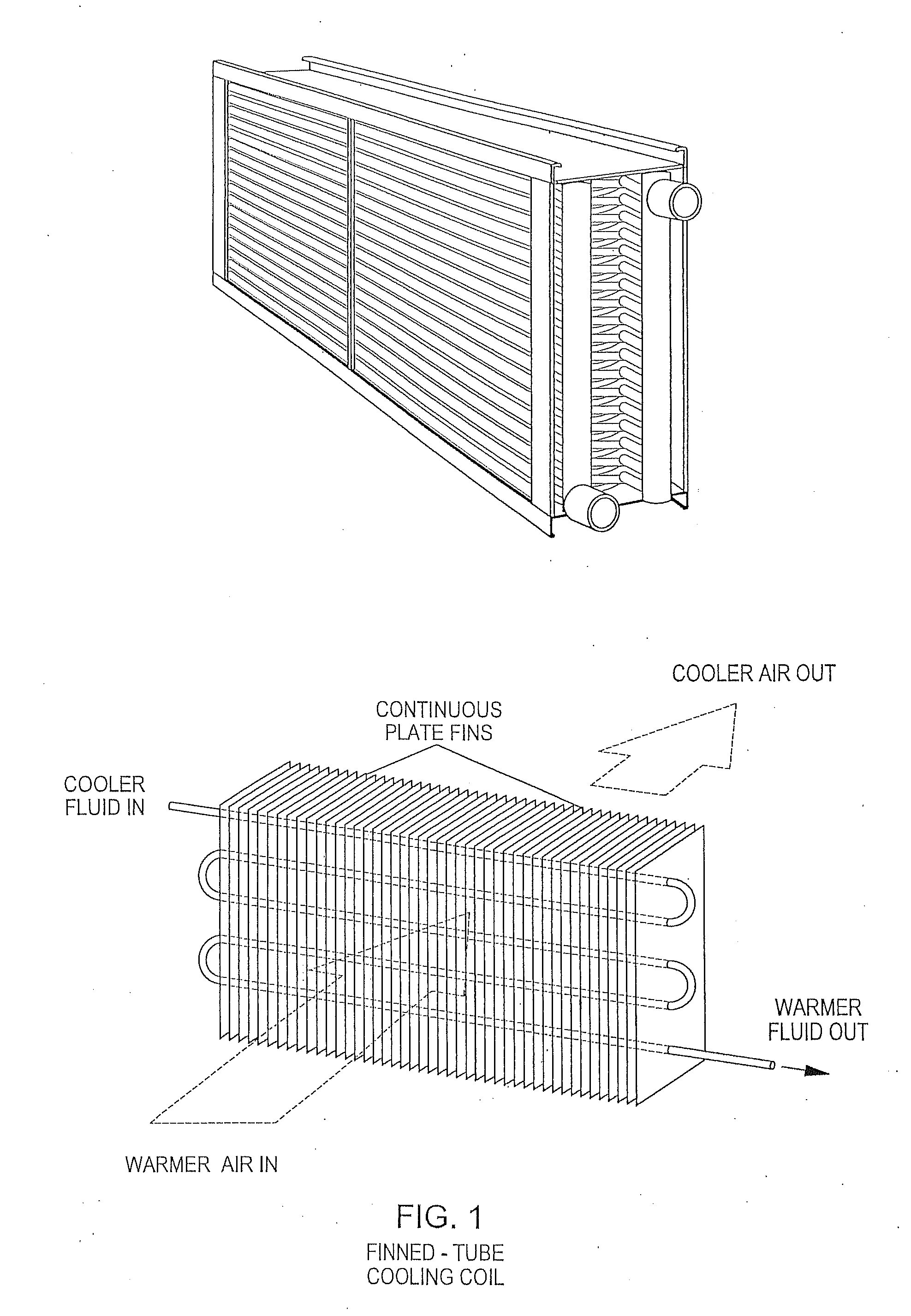
[0046]The device of this invention uses a reverse airflow arrangement to defrost a frosted cooling coil while not interrupting operation. Automatic air dampers are used to reverse the airflow when the defrost threshold is reached. Any type of serviceable damper such as a swing damper or a louvered damper can be used. This system is useful for low temperature cooling and dehumidification in situations where the cooling coil inlet air is above freezing, however exiting air below freezing can be supplied if desired. It is advantageous for operation if the coolant flow and temperature internal to the cooling coil are regulated to create the conditions for frost formation to begin closer to the air leaving side of the active cooling coil, and to regulate the rate of frost buildup to be consistent with the rate of defrosting.

[0047]FIG. 1 shows a schematic representation 1 of a typical cooling coil illustrating airflow through the cooling coil. Also shown in FIG. 1 is a perspective view of...


PUM


Abstract

A low temperature cooling and dehumidification system uses a reverse airflow arrangement to defrost a frosted cooling coil while not interrupting operation. Automatic air dampers are used to reverse the airflow at the proper time to initiate defrost of that section of frosted cooling coil. This system is useful for low temperature cooling and dehumidification in situations where the inlet air is above freezing, however exiting air below freezing can be supplied if desired. It is advantageous for operation if the coolant flow and temperature internal to the cooling coil are regulated to create the conditions for frost formation to begin closer to the air leaving side of the active cooling coil. The dehumidified generated condensate can be collected and used as grey water and/or potable water.

Description

FIELD OF THE INVENTION[0001]The present invention relates to using reverse airflow defrost in low temperature cooling and dehumidification systems, where inlet air is above freezing.BACKGROUND OF THE INVENTION[0002]Low temperature air cooling is needed to maintain low dew point temperatures in spaces such as hospital operating rooms, archival storage, indoor ice rinks, supermarkets etc. Mechanical cooling and dehumidification systems are generally restricted to delivering air temperatures safely above freezing to avoid complications associated with frost buildup in the cooling coil and subsequent air restriction.[0003]Cooling coils typically comprise tubes, through which flows a coolant such as water, brine or a refrigerant. The inner surface of the tubes can have enhancements to improve heat transfer between the coolant and the tube. Air, flows over the outside of the tubes where fins can be added to enhance heat transfer between the tube and air. The coolant inside the tubes remov...

Claims


Application Information

Patent Timeline
Patent Type & Authority Applications(United States)
IPC IPC(8): F25D21/12F25D21/14
CPCF25D21/14F25D21/125F24F12/001F24F2012/008F24F11/41Y02B30/56
Inventor STARK, WALTER
Owner KENTUCKIANA CURB
Why Eureka
Try Eureka