Margin improvement for configurable local clock buffer

Inactive Publication Date: 2015-03-26
GLOBALFOUNDRIES INC
View PDF3 Cites 3 Cited by
  • Summary
  • Abstract
  • Description
  • Claims
  • Application Information

AI Technical Summary

Benefits of technology

[0005]According to one exemplary embodiment, a timing margin circuit of a local clock buffer circuit located within a microelectronic device is provided. The timing margin circuit may include an inverter logic gate having an inverter input and an inverter output, whereby the inverter input receives an input clock signal. A NAND logic gate includes a first NAND input that is coupled to the inverter output, a second NAND input, and a NAND output. Also included is a logic device having a first logic device input that is coupled to the inverter output, a second logic device input that receives a mode selection signal, and a logic device output that couples to the second NAND input. The NAND logic gate generates, at the NAND output, a first time delayed input clock signal having a first time delay based on the mode selection signal being at a first logic state. The NAND logic gate also generates, at the NAND output, a second time delayed input clock signal having a second time

Problems solved by technology

A critical variability in device operation may, for example, be propagation delays through the device.
Thus, device size reductions leading to reduced operating voltages may create unpredictable variations in the propagation times (i.e., delay) th

Method used


Image

  • Margin improvement for configurable local clock buffer
  • Margin improvement for configurable local clock buffer
  • Margin improvement for configurable local clock buffer

Examples


Embodiment Construction

[0015]The following one or more exemplary embodiments describe a local clock buffer circuit that introduces a timing margin into controlling the clock signal in order to avoid race conditions.

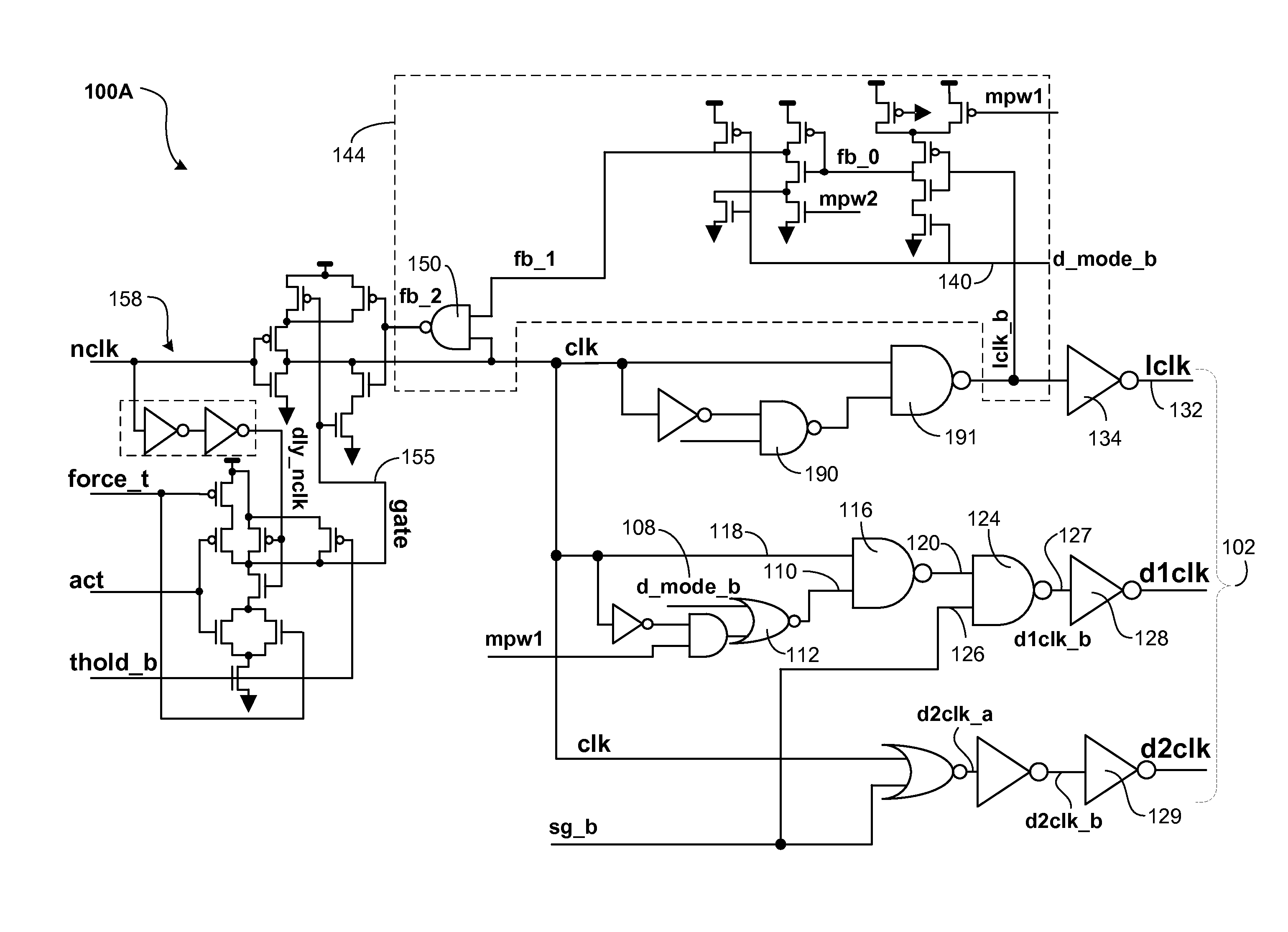
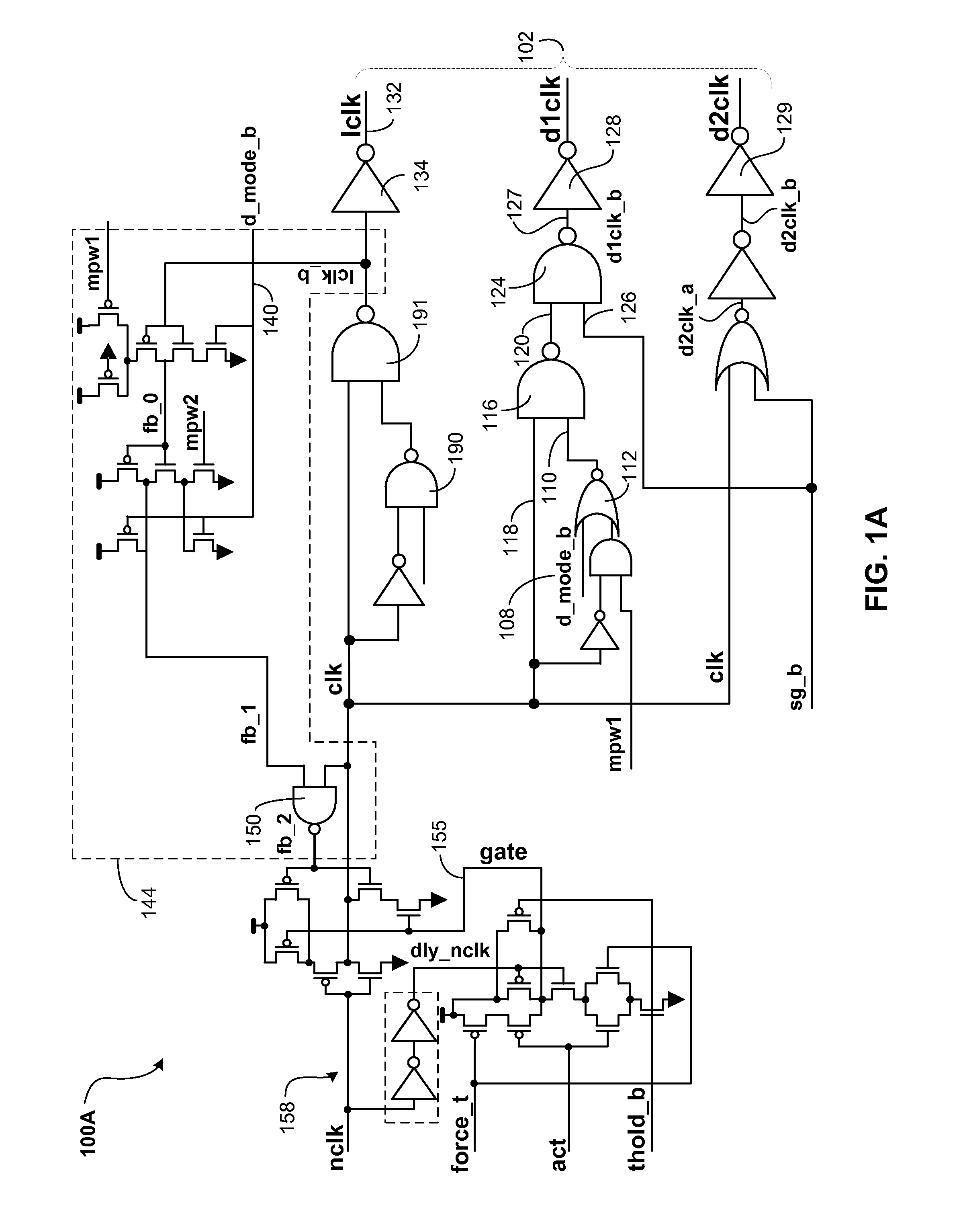
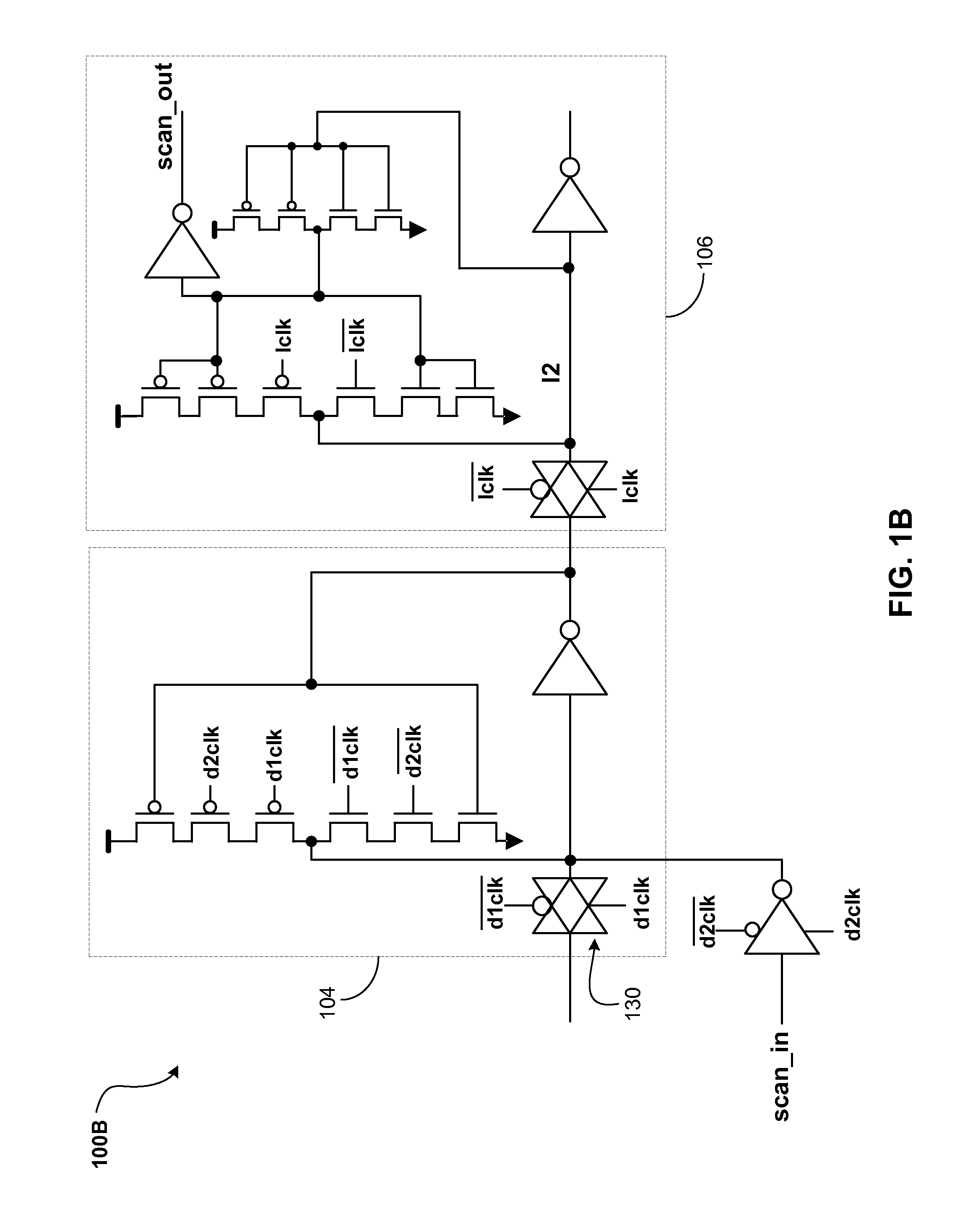
[0016]Referring to FIG. 1A, a local clock buffer circuit 100A may be used to drive sequential devices such as, for example, a plurality of latches (e.g., 30 latches). As depicted in FIG. 1B, the outputs 102 of the local clock buffer circuit 100A are used to drive an exemplary latch circuit 100B including a master latch 104 and a slave latch 106 stage. Specifically, the generated local clock signal lclk, the d1 clock d1clk, and the d2 clock d2clk of the local clock buffer circuit 100A, and their respective complementary signals (i.e., lclk, d1clk, d2clk), are driving latch circuitry 100B.

[0017]Referring to FIG. 1A, the d_mode_b control input 108 may be utilized to place the local clock buffer circuit 100A in either a self-timed pulse operating mode or in a master / slave type operating mode. For e...


PUM


Abstract

A timing margin circuit of a local clock buffer circuit may include an inverter logic gate having an inverter input and an inverter output, whereby the inverter input receives an input clock signal. A NAND logic gate includes a first NAND input coupled to the inverter output, a second NAND input, and a NAND output. The circuit also includes a logic device having a first logic device input that is coupled to the inverter output, a second logic device input that receives a mode selection signal, and a logic device output that couples to the second NAND input, whereby the NAND logic gate generates a first time delayed input clock signal and a second time delayed input clock signal, such that the first and the second time delayed input clock signal control a falling edge transition of a local clock signal derived from the input clock signal.

Description

BACKGROUND[0001]a. Field of the Invention[0002]The present invention generally relates to microelectronic devices, and more particularly to maintaining the timing performance of such microelectronic devices using clock buffer circuitry.[0003]b. Background of Invention[0004]As devices shrink, their operational variability also increases. Particularly, as new technologies emerge, in the interest of power consumption reduction, the device operating voltages also decrease with reduced device size. The impact of this device variability in turn may also be further increased by the reduced device operating voltages. A critical variability in device operation may, for example, be propagation delays through the device. Thus, device size reductions leading to reduced operating voltages may create unpredictable variations in the propagation times (i.e., delay) though the devices. In certain circuit implementations such as clock buffer circuits, these propagation delay changes may cause timing ...

Claims


Application Information

Patent Timeline
IPC IPC(8): H03K19/096
CPCH03K19/096
Inventor FLEISCHER, BRUCE M.WARNOCK, JAMES D.
Owner GLOBALFOUNDRIES INC
Why Eureka
Try Eureka