Portable type electronic device, portable type electronic device group, and method of manufacturing portable type electronic device

Active Publication Date: 2015-03-26
SONY COMPUTER ENTERTAINMENT INC
View PDF2 Cites 11 Cited by
  • Summary
  • Abstract
  • Description
  • Claims
  • Application Information

AI Technical Summary

Benefits of technology

[0010](4-1) In a mode of the present invention, an electronic device includes: a circuit board; and a housing including a front housing covering a front side of the circuit board and provided with a display screen and an operating member and a back housing covering a back surface side of the circuit board. In addition, the electronic device includes: an antenna housed in the housing; a communication module housed in the housing and transmitting and receiving a signal through the antenna; and a receiving device housed in the housing, the receiving device receiving an IC card used for communication by the antenna and the communication module. The antenna, the communication module, and the receiving device are disposed between the back housing and the circuit board. According to this mode, the front housing can be made common in the portable type electronic device including the antenna, the communication module, and the receiving device and a portable type electronic device not including these parts, and thus manufacturing cost of these portable type electronic devices can be reduced.
[0011](4-2) A portable type electronic device group according to a mode of the present invention includes a first portable type electronic device including a circuit board, a front housing covering a front side of the circuit board and provided with a display screen and an operating member, and a back housing covering a back side of the circuit board. The electronic device group also includes a second portable type electronic device including a circuit board, a front housing covering a front side of the circuit board and provided with a display screen and an operating member, and a back housing covering a back side of the circuit board, the second portable type electronic device not having a part of functions provided to the first portable type electronic device. The first electronic device has a plurality of parts for the

Problems solved by technology

However, because the cable usually has a surplus length, the position of the cable is not easily fixed within the electronic device.
Therefore, when the cable is disposed in a narrow space within the electronic device, the cable and other parts tend to interfere with each other.
(3) When one circuit board coinciding in size with the housing in the electronic device is used, the following inconvenience may arise.
When the whole of one circuit board coinciding in size with the housing has multiple layers or a high-strength material is used f

Method used


Image

  • Portable type electronic device, portable type electronic device group, and method of manufacturing portable type electronic device
  • Portable type electronic device, portable type electronic device group, and method of manufacturing portable type electronic device
  • Portable type electronic device, portable type electronic device group, and method of manufacturing portable type electronic device

Examples


Embodiment Construction

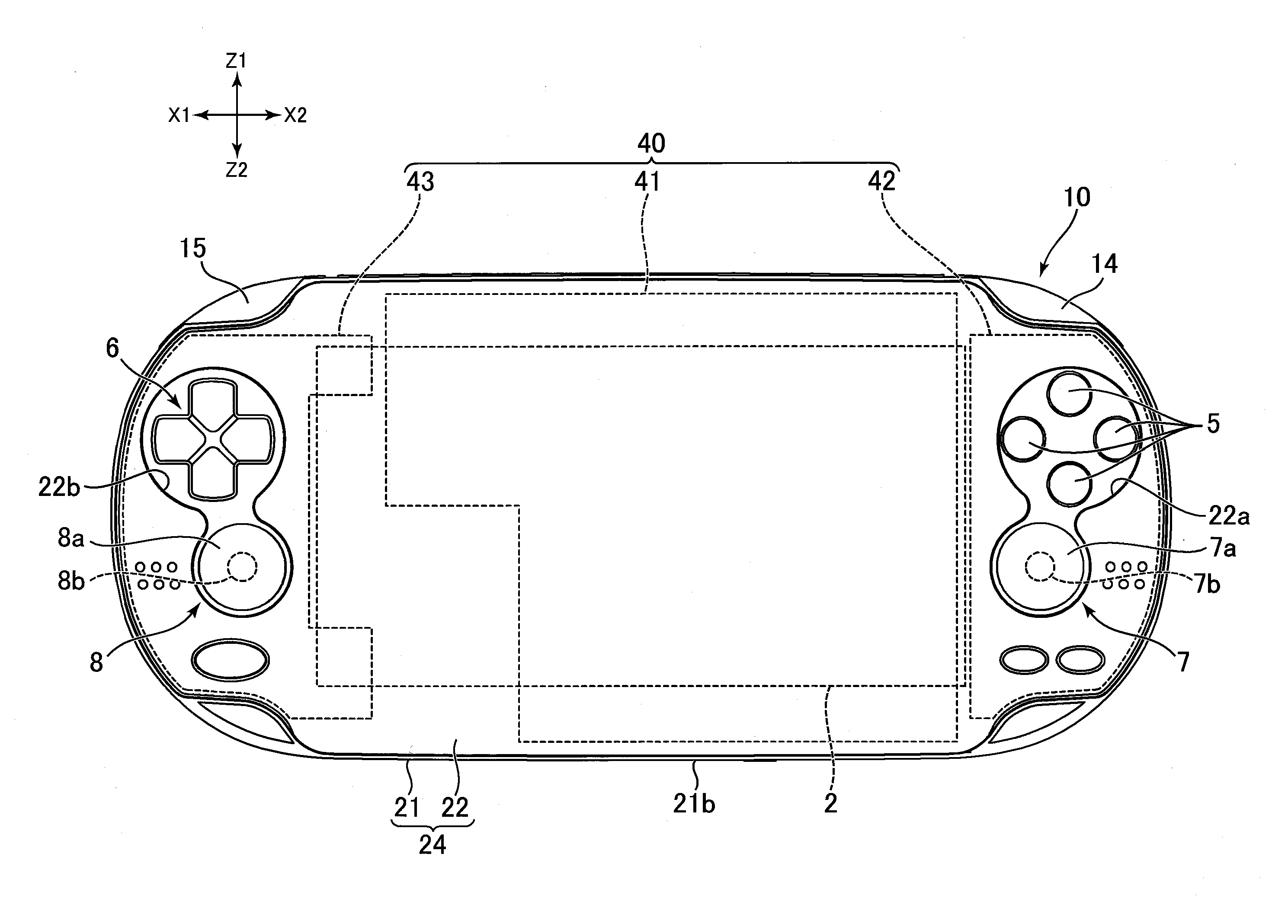
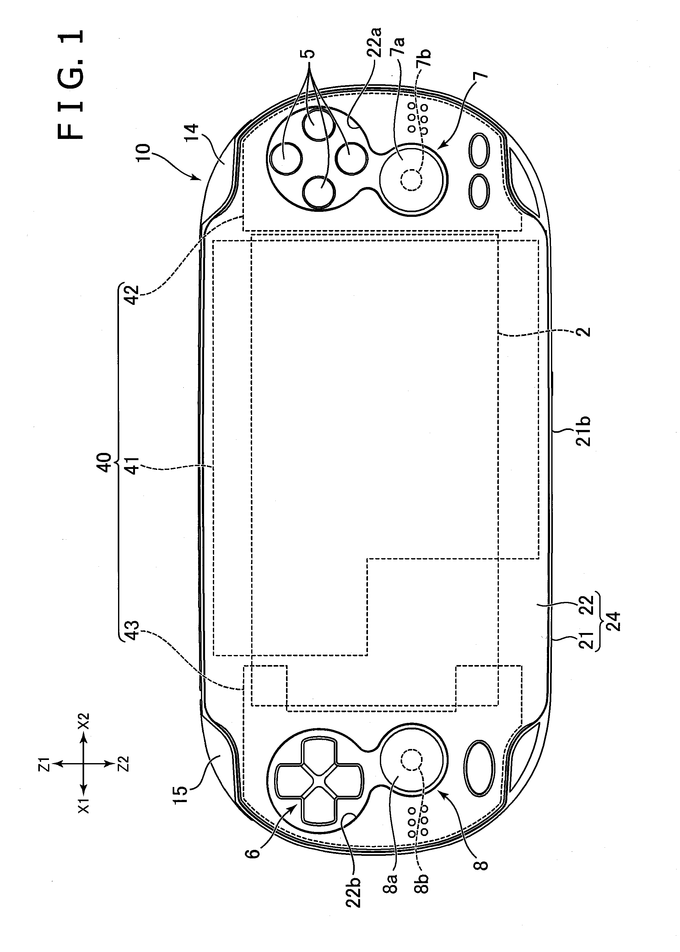
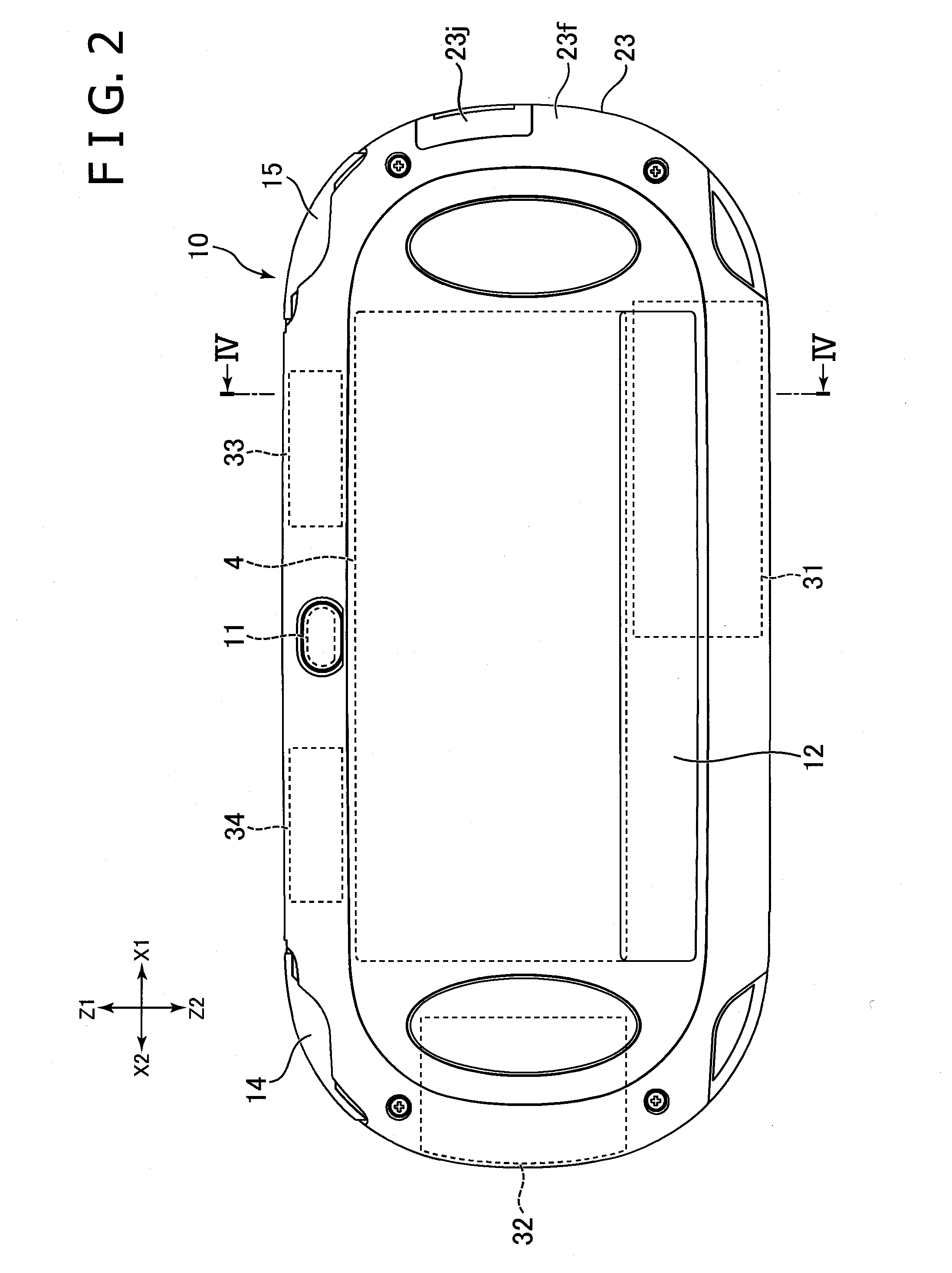
[0027]An embodiment of the present invention will hereinafter be described with reference to the drawings. FIG. 1 is a front view of a portable type electronic device 10 according to an embodiment of the present invention. FIG. 2 is a rear view of the electronic device 10. FIG. 3 is an exploded perspective view of the electronic device 10. FIG. 4 is a sectional view of a housing, the section being taken along a line IV-IV shown in FIG. 2.

[0028]Incidentally, the following description, directions denoted by X1 and X2 in FIG. 1 are a left direction and a right direction, respectively, and directions denoted by Z1 and Z2 in FIG. 1 are an upward direction and a downward direction, respectively. In addition, directions denoted by Y1 and Y2 in FIG. 4 are a front direction and a rear direction, respectively.

[General Constitution]

[0029]The electronic device 10 has a housing 20 that houses a circuit board 40 and the like and which forms an external surface of the electronic device 10. As show...


PUM


Abstract

A first antenna (31) is disposed closer to a rear touch panel (4) than to a display panel (2a) in the front-rear direction of a housing (20). The first antenna (31) is disposed so as to be offset with respect to the rear touch panel (4) in a direction perpendicular to the front-rear direction of the housing (20) so that at least a part of the first antenna (31) does not overlap the rear touch panel (4) in the front-rear direction of the housing (20). With such a structure, the display panel and touch panel are provided at the front surface and rear surface, respectively, and good reception sensitivity can be obtained.

Description

TECHNICAL FIELD[0001]The present invention relates to a portable type electronic device, a portable type electronic device group, and a method of manufacturing the portable type electronic device.BACKGROUND ART[0002](1) Conventionally, portable type electronic devices capable of wireless communication using a mobile telephone network and wireless communication using a wireless LAN have been used. Electronic devices of this type include an antenna (see for example US 2007 / 0,202,956 A1).[0003](2) In addition, inside a portable type electronic device, an IC chip mounted on a circuit board and other electronic parts included in the electronic device may be connected to each other via a cable.[0004](3) In addition, as disclosed in US 2007 / 0,202,956 A1, portable type electronic devices having a wireless communication function have been conventionally used. The frequencies of radio waves used in wireless communication have recently been increased. It is desired that electronic devices hand...

Claims


Application Information

Patent Timeline
IPC IPC(8): G06F1/16
CPCG06F1/1658G06F1/1698H04M1/026H05K1/14H05K1/18A63F2300/204A63F2300/1043A63F2300/1068H04M2250/22A63F2300/1075A63F13/24A63F13/2145A63F13/92A63F13/214A63F13/90
Inventor SAKAKIBARA, KENJIMASUDA, HIROAKITOGASAKI, YUMIYAZAWA, KIYOKAZUNAKAGAWA, KAZUTO
Owner SONY COMPUTER ENTERTAINMENT INC
Why Eureka
Try Eureka