Panel for display device, display device, and method for testing panel for display device

a display device and panel technology, applied in static indicating devices, emergency protective arrangements for limiting excess voltage/current, instruments, etc., can solve problems such as difficulty in normal emission testing, and achieve the effect of suppressing the increase in power consumption during normal operation

Active Publication Date: 2015-04-02
JOLED INC
View PDF2 Cites 25 Cited by
  • Summary
  • Abstract
  • Description
  • Claims
  • Application Information

AI Technical Summary

Benefits of technology

[0012]With the panel for a display device and the method for testing the panel according to the present disclosure, an emission test can be normally performed, and an increase in power consumption during usual operation can be suppressed.

Problems solved by technology

However, it is difficult to normally perform an emission test while achieving reduction of the occurrence of adverse effects during usual operation.

Method used


Image

  • Panel for display device, display device, and method for testing panel for display device
  • Panel for display device, display device, and method for testing panel for display device
  • Panel for display device, display device, and method for testing panel for display device

Examples


first embodiment

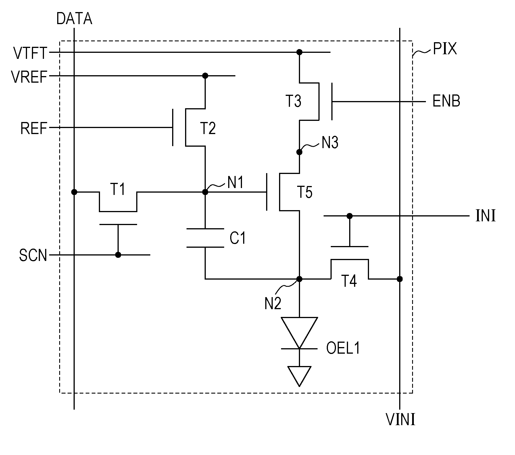
[0065]A panel for a display device, a display device including the panel, and a method for testing the panel according to a first embodiment will be described with reference to FIGS. 1 to 9.

1-1. Display Device

[0066]The configuration of the display device according to the first embodiment will be described with reference to FIGS. 1 to 4. The display device according to the first embodiment is an organic EL display.

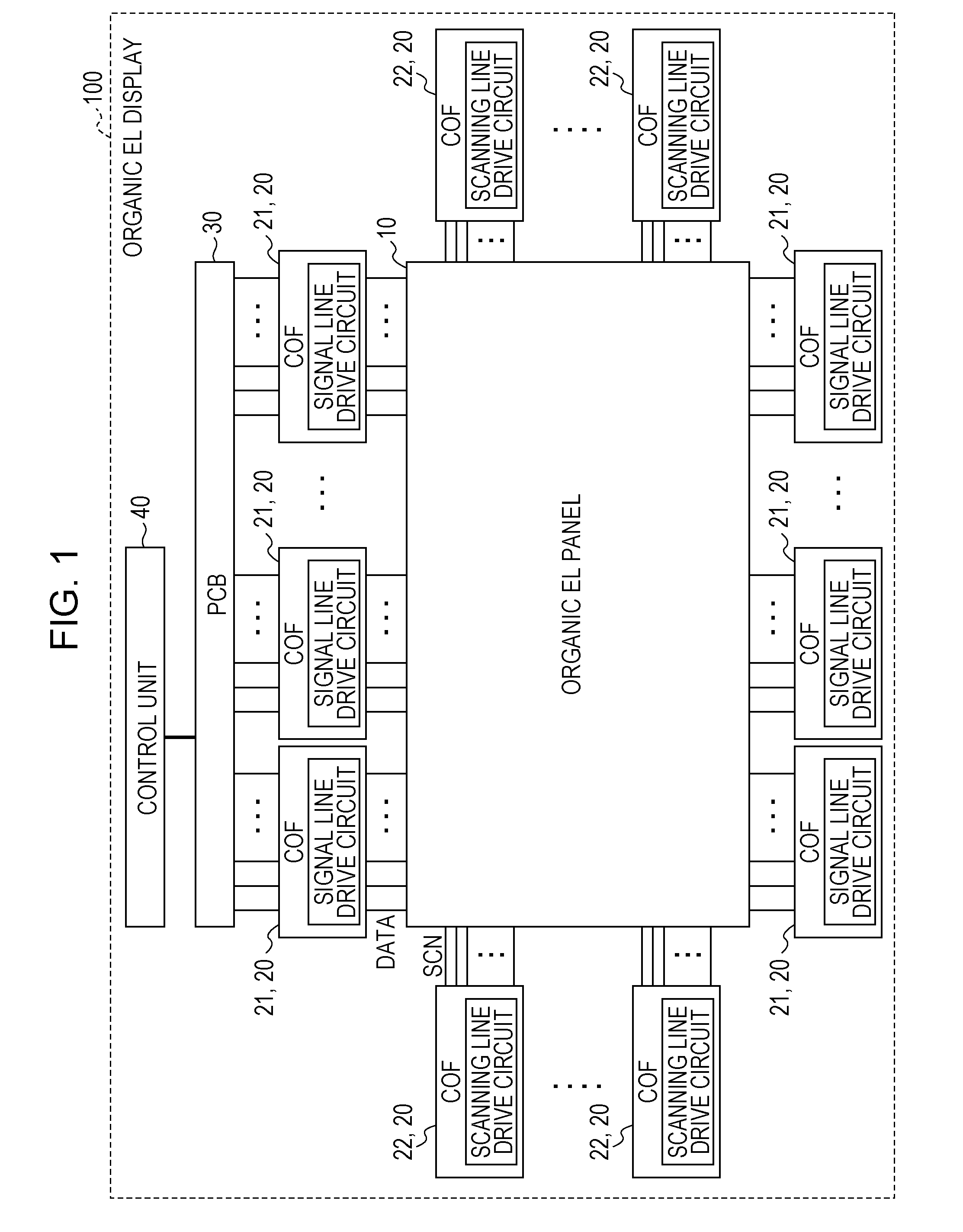
[0067]FIG. 1 is a block diagram illustrating an example of the configuration of an organic EL display 100.

[0068]As illustrated in FIG. 1, the organic EL display 100 includes an organic EL panel 10A (10), chip on film (or chip on flexible: COF) circuits 20, a printed circuit board (PCB) 30, a control unit 40, and a power supply circuit (not illustrated).

[0069]The organic EL panel 10 is an example of a panel for a display device.

1-1-1. Configuration of Organic EL Panel (Panel for Display Device)

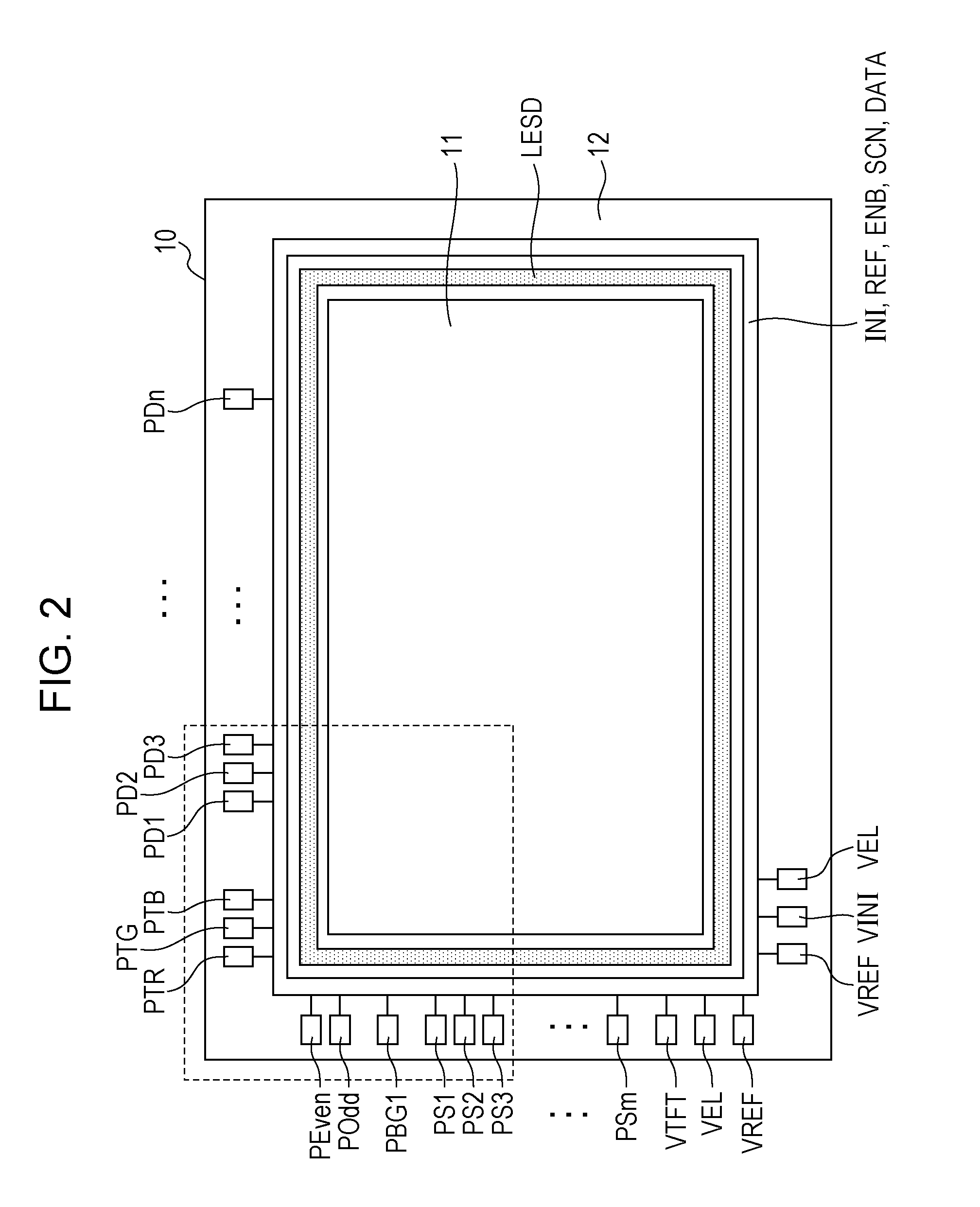
[0070]The organic EL panel 10A according to the first embodiment is a panel for di...

second embodiment

[0137]A panel for a display device, a display device including the panel, and a method for testing the panel according to a second embodiment will be described with reference to FIG. 10.

[0138]The display device according to the second embodiment is different from the display device according to the first embodiment in the configuration of the panel (organic EL panel). The method for testing the panel according to the second embodiment is the same as the method according to the first embodiment.

[0139]The display device according to the second embodiment is the organic EL display 100, as in the first embodiment. The organic EL display 100 includes an organic EL panel 10B (10), the COF circuits 20, the PCB 30, the control unit 40, and the power supply circuit (not illustrated). The configurations of the COF circuits 20, the PCB 30, the control unit 40, and the power supply circuit are the same as those in the first embodiment.

2-1. Configuration of Organic EL Panel (Panel for Display De...

third embodiment

[0150]A panel for a display device, a display device including the panel, and a method for testing the panel according to a third embodiment will be described with reference to FIGS. 11 to 13.

[0151]The display device according to the third embodiment is different from the display device according to the first embodiment in the configuration of the panel (organic EL panel). The method for testing the panel according to the third embodiment is the same as the method according to the first embodiment.

[0152]The display device according to the third embodiment is the organic EL display 100, as in the first embodiment. The organic EL display 100 includes an organic EL panel 10C (10), the COF circuits 20, the PCB 30, the control unit 40, and the power supply circuit (not illustrated). The configurations of the COF circuits 20, the PCB 30, the control unit 40, and the power supply circuit are the same as those in the first embodiment.

3-1. Configuration of Organic EL Panel (Panel for Display...


PUM


Abstract

A panel for a display device includes a display unit, an electrostatic protection wire, a wire being connected to the display pixels, an electrostatic protection circuit, and an electrostatic protection circuit control line. The display unit includes a plurality of display pixels. The electrostatic protection wire is connected to a test pad, the test pad being provided to receive a test signal. The electrostatic protection circuit connects the electrostatic protection wire and the wire connected to the display pixels. The electrostatic protection circuit includes a back-gate-type transistor that has a gate electrode, a drain electrode being short-circuited with the gate electrode, and a back-gate electrode. The electrostatic protection circuit control line includes a first end and a second end, the first end being connected to the back-gate electrode of the back-gate-type transistor.

Description

BACKGROUND OF THE DISCLOSURE[0001]1. Field of the Disclosure[0002]The present disclosure relates to a panel for a display device including organic electroluminescence (EL) elements, a display device, and a method for testing a panel for a display device.[0003]2. Description of the Related Art[0004]An organic EL display including organic EL elements is a known example of an image display device including current-driven light-emitting elements. The organic EL display has advantages of favorable viewing-angle characteristics and low power consumption.[0005]The organic EL display includes an organic EL panel (display panel) including a glass substrate on which organic EL elements, wires, and so forth are formed, an integrated circuit (IC) for driving the organic EL panel, a control circuit, and so forth.[0006]When organic EL displays are manufactured, organic EL panels are tested, after being manufactured, to determine whether or not the panels normally emit light. After the emission te...

Claims


Application Information

Patent Timeline
Patent Type & Authority Applications(United States)
IPC IPC(8): H05B33/08H02H9/04G09G3/30G09G3/00H05B44/00
CPCH05B33/08G09G3/30H02H9/044G09G3/006G09G3/3233G09G2300/0861G09G2330/08H05B45/60Y02B20/30
Inventor EBISUNO, KOUHEI
Owner JOLED INC
Why Eureka
Try Eureka