Virtual Circuit Breaker

a virtual circuit and circuit breaker technology, applied in the direction of emergency protection for supplying operative power, electrical equipment, arrangements resposes to fault current, etc., can solve the problems of high cost and/or volume, large installation volume, and ineffective cost and/or volume of sspcs for higher power loads, so as to prevent or mitigate potential damage and/or harm

Inactive Publication Date: 2015-04-02
ASTRONICS ADVANCED ELECTRONICS SYST
View PDF5 Cites 4 Cited by
  • Summary
  • Abstract
  • Description
  • Claims
  • Application Information

AI Technical Summary

Benefits of technology

[0007]Disclosed is a virtual circuit breaker (VCB) having an electrical relay and a control circuit. The electrical relay is effective to control the power flow of a power line. The control circuit has a load and wire protection (“OC”) detection unit, a microprocessor and a driver. When an overload or short circuit condition is detected, the driver receives a command that the relay should stop the flow of power in the power line and, in return, the relay is caused to shut off power flow in the line, thus preventing or mitigating potential damage and / or harm.
[0011]Another advantage is that utilization of the disclosed subject matter may decrease overall project costs, depending in part on the load rating of any particular implementation.
[0012]Yet another advantage of the disclosed subject matter is that it allows for the utilization of conventional, proven components such as off the shelf (OTS) power relays and control circuits. This may, in turn, result in schedule and project cost reductions.

Problems solved by technology

The thermal circuit breaker / power relay solution has a long service history, but this combination can be bulky and labor intensive for installation and trouble shooting.
However, SSPCs are not cost and / or volume effective for higher power loads, largely due to the fact such applications require a high number of metal-oxide-semiconductor field-effect transistors (MOSFETs).

Method used


Image

  • Virtual Circuit Breaker
  • Virtual Circuit Breaker
  • Virtual Circuit Breaker

Examples


Embodiment Construction

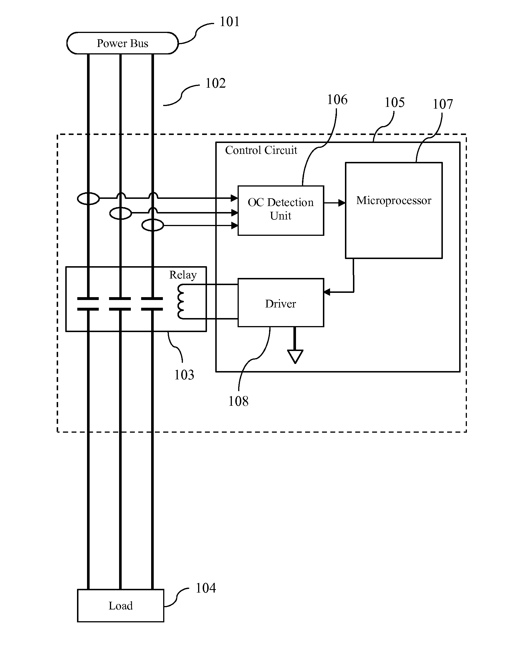
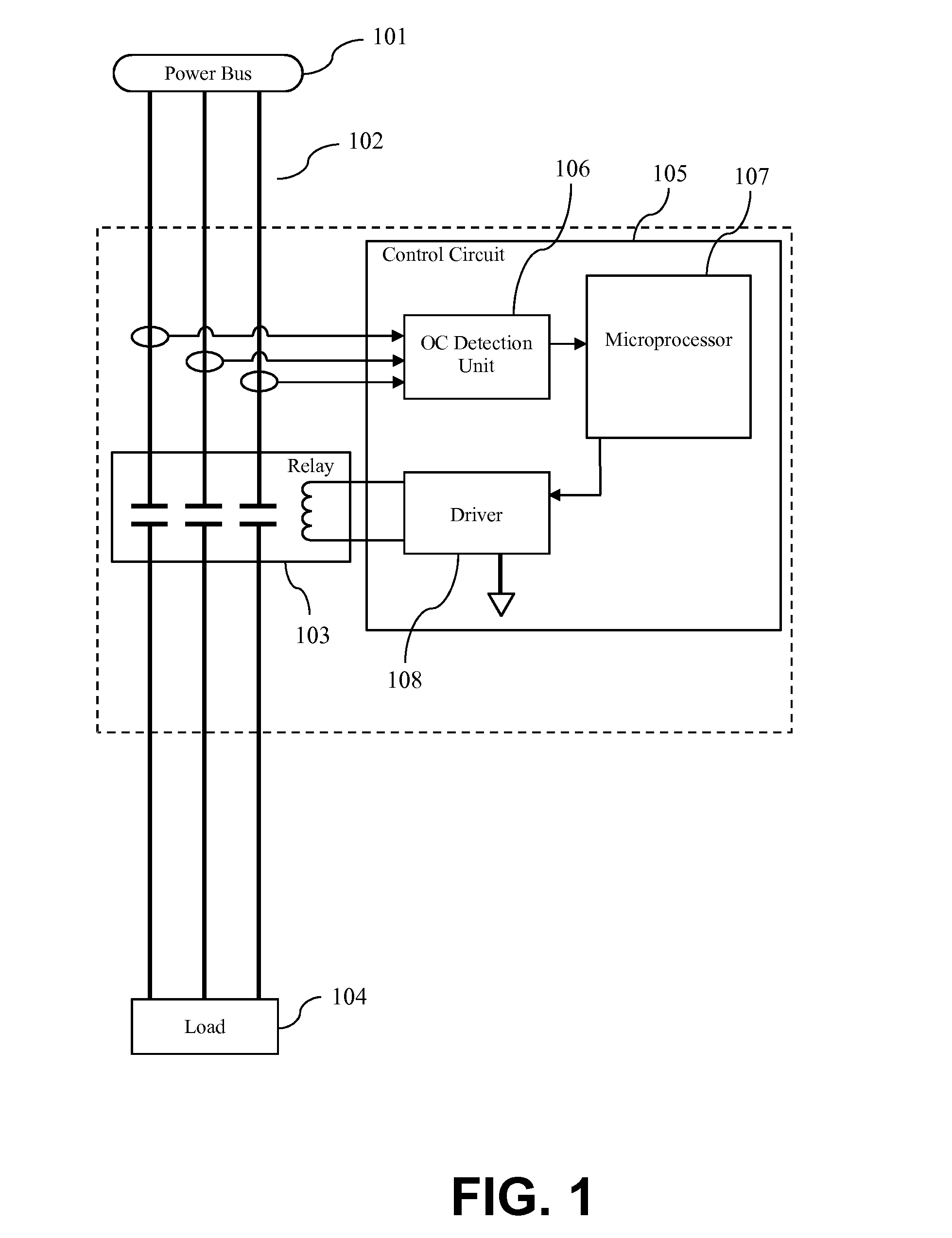
[0019]FIG. 1 is a schematic diagram of one embodiment VCB. A power bus 101, which may be a source of limited power, such as a generator on an aircraft, supplies an amount of power flow along power line 102, which is in this embodiment carrying 3-phase AC power. It should be understood that the disclosed subject matter can be utilized with 1-phase AC and 3-phase AC power, as well as other power configurations, including without limitation 28 VDC and 270 VDC. Electrical relay 103 is effective to control this power flow. For example, relay 103 can allow power to flow from power bus 101 to load 104 or, inversely, prevent such flow. Various electrical relays are suitable for use with the disclosed subject matter, including by way of example commercially available OTS units. Control circuit 105 includes OC detection unit 106, microprocessor 107 and driver 108. Upon receipt of a deactivation command, driver 108 is effective to cause relay 103 to stop the flow of power in power line 102. OC...


PUM


Abstract

A virtual circuit breaker having an electrical relay and a control circuit, the control circuit including a load and wire protection (“OC”) detection unit, a microprocessor and a driver. The OC detection unit is configured to monitor a power flow and the electrical relay is effective to control it. The driver is effective to cause the relay to stop the power flow upon receipt of a deactivation command. The OC detection unit is effective to cause the driver to receive a deactivation command if the OC detection unit senses that a short circuit condition or an overload condition exists. The microprocessor of the control unit is configured so as to be capable of, at least, receiving input from the OC detection unit and sending output to the driver.

Description

FIELD OF THE DISCLOSURE[0001]The subject matter of the present disclosure generally relates to circuit control devices, and more particularly relates to virtual circuit breakers utilizing microprocessors.BACKGROUND OF THE DISCLOSURE[0002]Control devices for circuits are important in many electrical applications. For instance, various circuit breaker designs that are useful in numerous applications have been previously developed and disclosed.[0003]In current aerospace power distribution systems, electrical loads are fed through a thermal circuit breaker and a power relay connected in-series, in order to provide load and wire protection (over-current or “OC”) and load On / Off control (switching). Alternatively, a Solid State Power Controller (SSPC) may be used to perform these same functions.[0004]The thermal circuit breaker / power relay solution has a long service history, but this combination can be bulky and labor intensive for installation and trouble shooting. The SSPC solution ha...

Claims


Application Information

Patent Timeline
Patent Type & Authority Applications(United States)
IPC IPC(8): H02H3/10H02H3/16
CPCH02H3/16H02H3/10H02H1/06H02H3/08
Inventor VAZIRI, MASSOUD
Owner ASTRONICS ADVANCED ELECTRONICS SYST
Why Eureka
Try Eureka