Optimal sensor and actuator deployment for system design and control

a technology of optimal positioning and actuators, applied in the direction of design optimisation/simulation, instruments, computation using non-denominational number representation, etc., can solve the problems of too complicated for application to typical consumer applications, too complex theoretic complexity, and too complicated for typical consumer applications to achieve the effect of reducing the complexity of the problem

Inactive Publication Date: 2015-04-02
NEC LAB AMERICA
View PDF0 Cites 26 Cited by
  • Summary
  • Abstract
  • Description
  • Claims
  • Application Information

AI Technical Summary

Benefits of technology

[0009]In another embodiment, the present disclosure provides a non-transitory computer program product comprising a computer readable storage medium having computer readable program code embodied therein for performing a method for determining the location of actuators and sensors for climate control. The method may include providing a model of temperature and airflow within a room. The model includes a plurality of temperature and time transition states in a grid corresponding to a geometry of the room. A matrix for the placement of sensors is calculated from the model using a Lyapunov equation in which a variable for the Lyapunov equation includes a matrix for the transition state of temperature obtained from the model of temperature and airflow within the room. A trace of the matrix for the placement of sensors is maximized to provide optimum placement of the sensors within the room. A matrix for calculating the placement of actuators within the model using the Lyapunov equation is also calculated in which a variable for the Lyapunov equation includes the matrix for the transition state obtained from the model of temperature and airflow within the room. A trace of the matrix for the placement of actuators is maximized to provide optimum placement of the actuators within the room.

Problems solved by technology

Existing technology rarely deals with how to best place the sensors and actuators, but instead focuses on temperature monitoring and control with sensors and actuators having already been placed.
From a practical view of point, these studies, due to their theoretical complexity, are too complicated for application to typical consumer applications.
However, the solutions developed are either heuristic or rather complicated involving optimization methods, such as large-scale nonlinear integer programming.

Method used


Image

  • Optimal sensor and actuator deployment for system design and control
  • Optimal sensor and actuator deployment for system design and control
  • Optimal sensor and actuator deployment for system design and control

Examples


Embodiment Construction

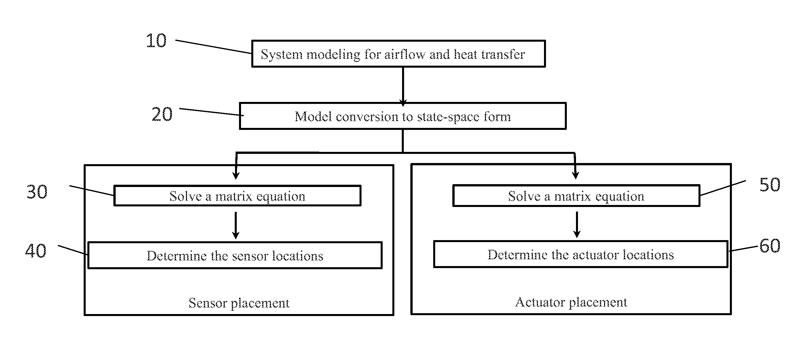
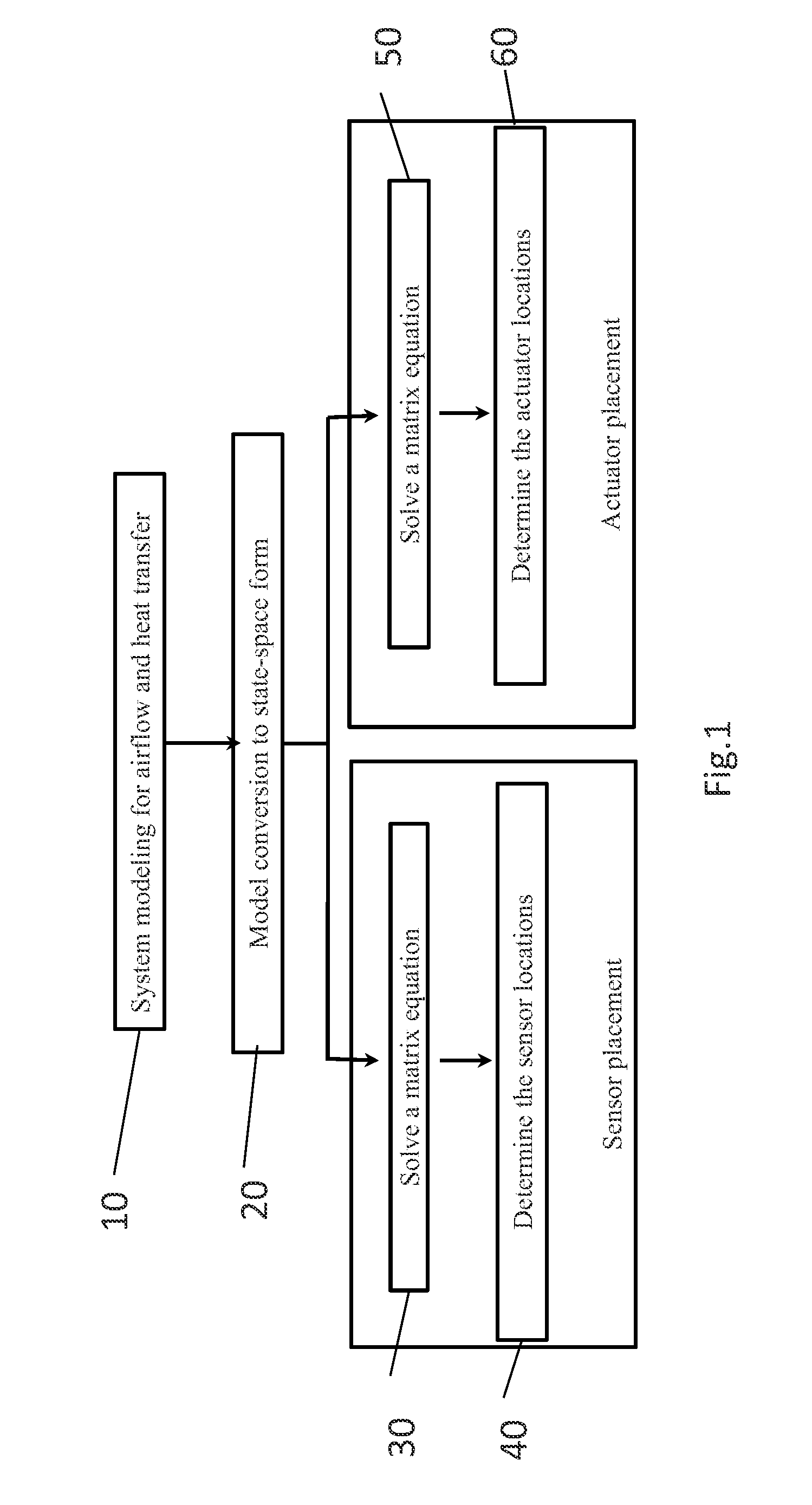
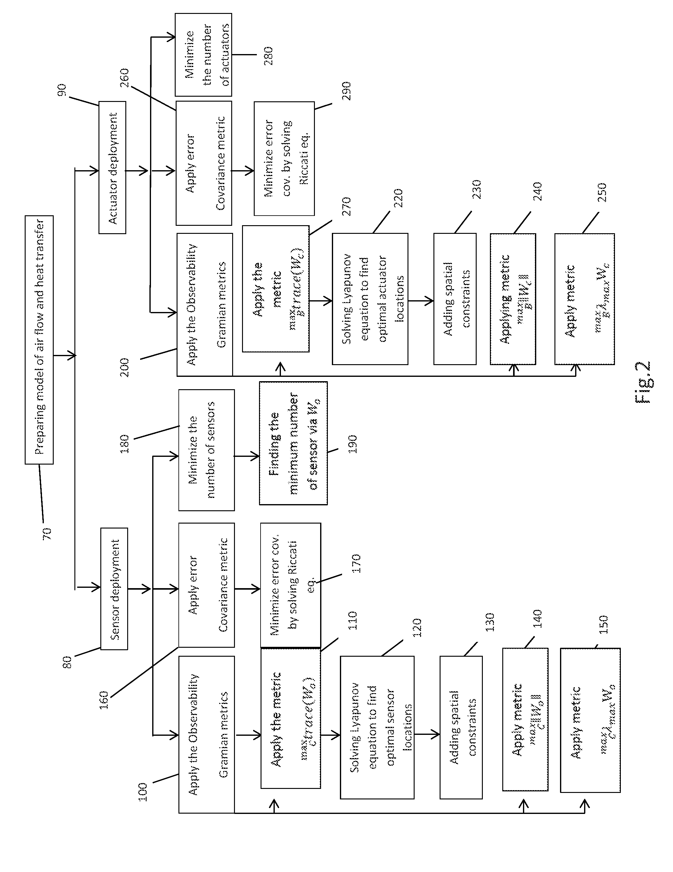
[0015]The present principles are directed to strategies for optimal placement of sensors (for temperature or climate measurements) and actuators (such as air conditioning (A / C) devices) for a given room. In some embodiments, the strategies disclosed herein optimally place sensors and actuators in a large space such that the temperature can be better monitored and regulated. The strategies can be constructed within a solid theoretical framework and have practical significance for HVAC system design with manageable computational cost.

[0016]It should be understood that embodiments described herein may be entirely hardware or may include both hardware and software elements, which includes but is not limited to firmware, resident software, microcode, etc.

[0017]Embodiments may include a computer program product accessible from a computer-usable or computer-readable medium providing program code for use by or in connection with a computer or any instruction execution system. A computer-usa...


PUM


Abstract

A method of determining the location of actuators and sensors for climate control that includes providing a model of temperature and airflow within a room. A matrix for the placement of sensors is calculated using a Lyapunov equation. A Lyapunov equation includes a matrix for the transition state from the model of temperature and airflow. A trace of the matrix for the placement of sensors is maximized to provide optimum placement of the sensors. A matrix for the placement of actuators within the model is calculated using the Lyapunov equation. A variable for the Lyapunov equation includes the matrix for the transition state obtained from the model of temperature and airflow. A trace of the matrix for the placement of actuators is maximized to provide optimum placement of the actuators within the room.

Description

RELATED APPLICATION INFORMATION[0001]This application claims priority to provisional application Ser. No. 61 / 885,564 filed on Oct. 2, 2013, incorporated herein by reference.BACKGROUND[0002]1. Technical Field[0003]The present invention relates to strategies for optimal placement of sensors and actuators for temperature control, and more particularly to the placement of sensors for temperature and climate measurements and the placement of air conditioning devices for a given room.[0004]2. Description of the Related Art[0005]Traditional sensor and actuator deployment for climate control depends almost solely on heuristic rules. Existing technology rarely deals with how to best place the sensors and actuators, but instead focuses on temperature monitoring and control with sensors and actuators having already been placed. Literature on optimal sensor and actuator placement for HVAC system design is mainly on the theoretical analysis of dynamic models comprised of partial differential equ...

Claims


Application Information

Patent Timeline
Patent Type & Authority Applications(United States)
IPC IPC(8): G06F17/50G06F17/11
CPCG06F17/11G06F17/5009G06F30/13G06F2119/08
Inventor PATIL, RAKESHFANG, HUAZHENSHARMA, RATNESH
Owner NEC LAB AMERICA
Why Eureka
Try Eureka