
Systems and methods for converting biomass to biocrude via hydrothermal liquefaction

Active Publication Date: 2015-04-09
BOARD OF RGT THE UNIV OF TEXAS SYST
View PDF2 Cites 6 Cited by
  • Summary
  • Abstract
  • Description
  • Claims
  • Application Information

AI Technical Summary

Benefits of technology

The patent describes a system and process for converting biomass to biocrude using a hydrothermal liquefaction reactor. The system includes a solar thermal energy collection system that provides concentrated solar energy to the reactor for heating the biomass slurry. The solar thermal energy is collected using a concentrated solar thermal energy concentrating mechanism, such as a dish or mirror, and a receiver. The system also includes a pump for continuously pumping the biomass slurry through the reactor. The process of converting biomass to biocrude involves heating the biomass slurry with the concentrated solar energy and using the heat to drive a generator for powering the pump. The generated electrical energy and any remaining thermal energy from the combustion of the biogas is then used to heat the reactor. The system may also include an anaerobic digester for generating biogas and a heat exchanger for harvesting the thermal energy from the combustion of the biogas. The technical effects of the patent include improved thermal energy utilization and reduced costs for the production of biocrude.

Problems solved by technology

Today, we face a challenge in meeting these mandates partly because of the energy requirements of generating advanced biofuels as well as sourcing an adequate supply of reliable feedstocks.
Since specific high lipid-yielding microalgae are selected for cultivation, contaminants such as other species of algae and predators only lower expected lipid yields.
However, one of the main barriers preventing the widespread adoption of the HTL technology to produce renewable fuels has been the high energy requirement to drive the HTL reactor, which requires temperatures of around 400° C. and pressures of around 20 MPa.
Traditionally, the HTL process requires a prohibitively large energy input that in turn renders the process with a negative EROI.

Method used


Image

  • Systems and methods for converting biomass to biocrude via hydrothermal liquefaction
  • Systems and methods for converting biomass to biocrude via hydrothermal liquefaction
  • Systems and methods for converting biomass to biocrude via hydrothermal liquefaction

Examples


Embodiment Construction

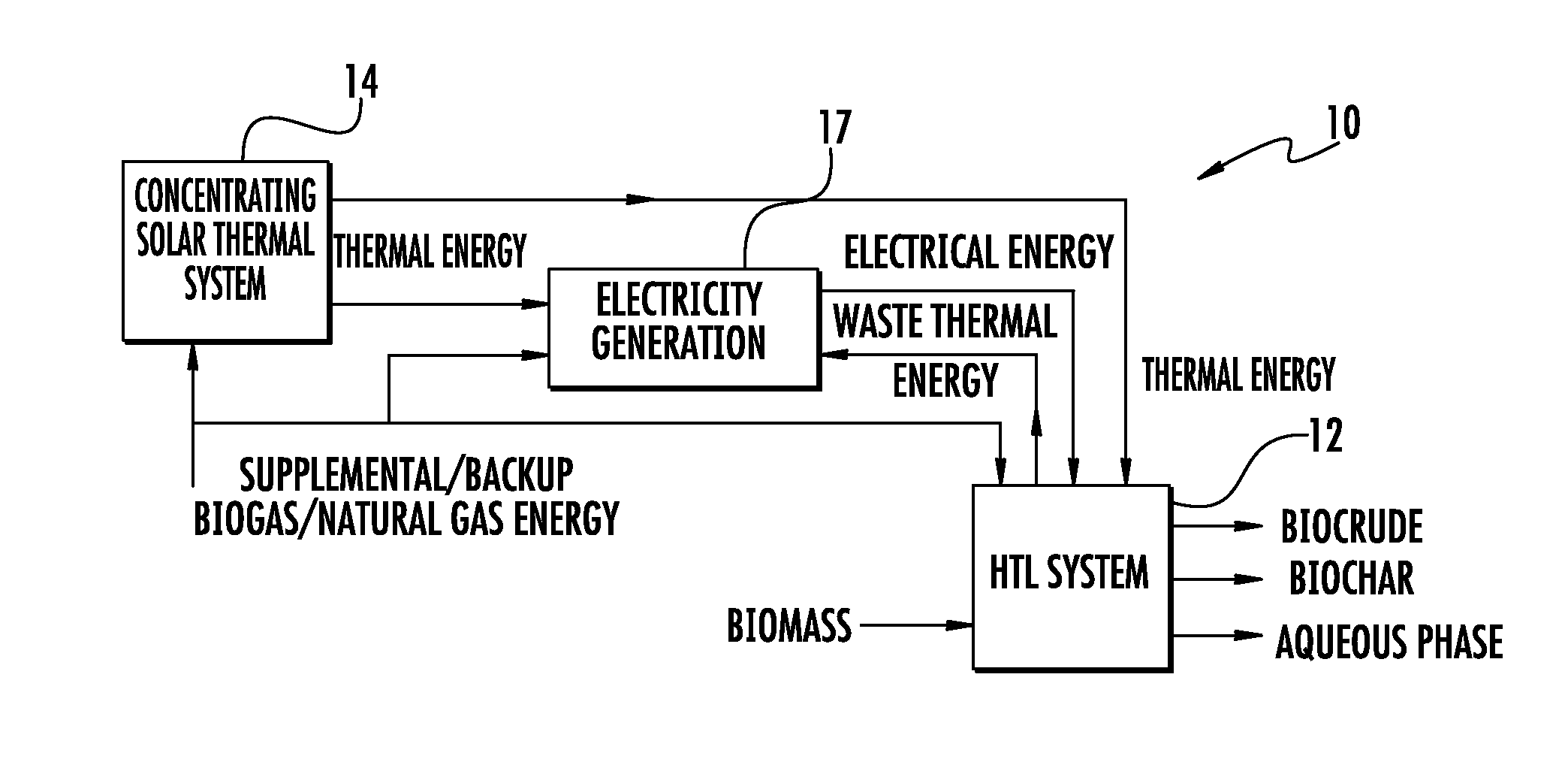
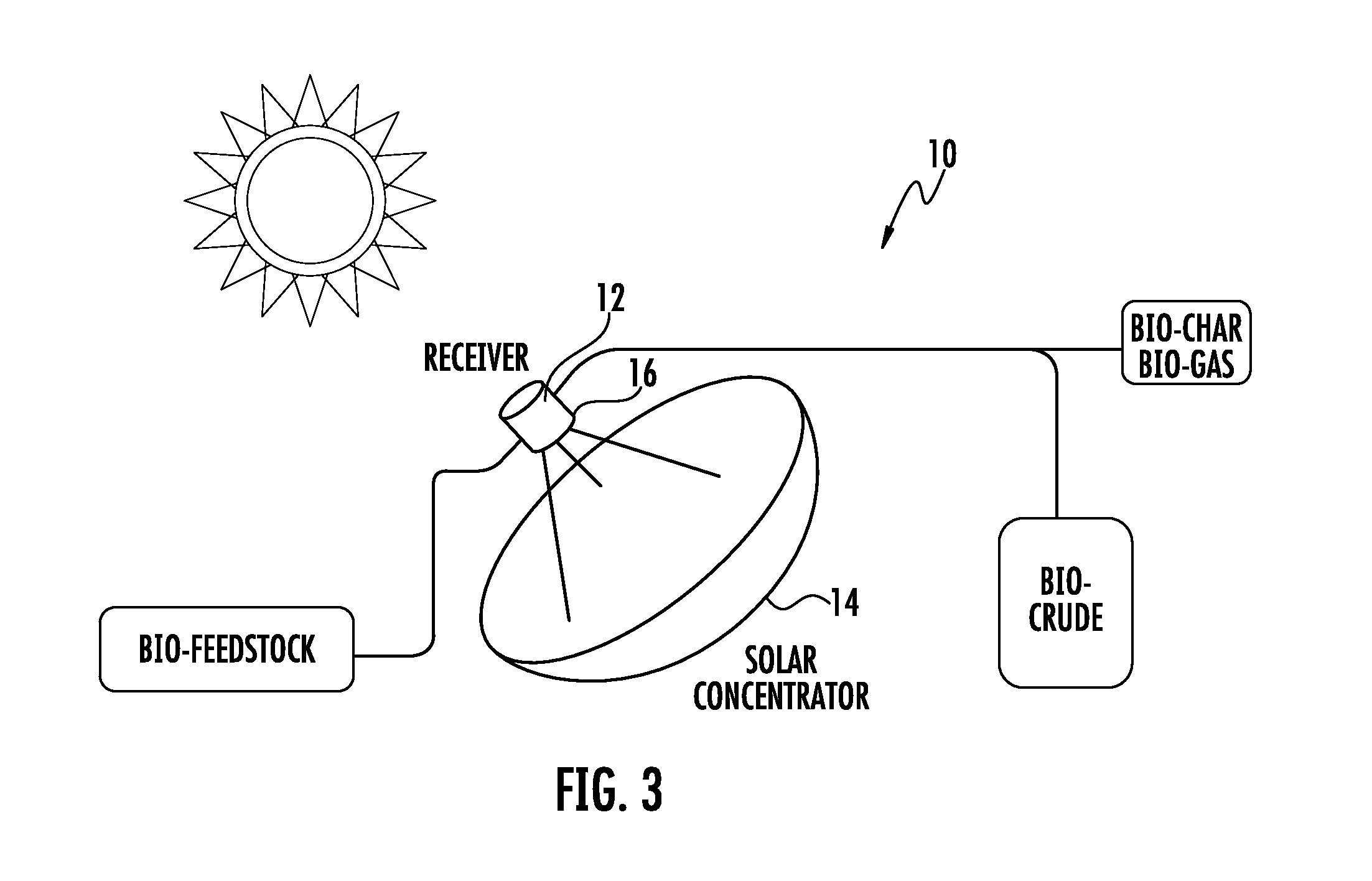
[0030]Described herein are systems and processes of providing novel thermal energy sources for hydrothermal liquefaction (HTL) reactors. For example, various implementations include a novel hydrothermal liquefaction (HTL) reactor that uses solar thermal concentration technology in a novel way such that the energy barrier for the HTL process is removed. According to various implementations, the systems and processes use concentrated solar thermal energy from a focused high-energy beam to provide sufficient energy for driving the HTL biomass-to-biocrude process. The concentrated solar thermal energy may be collected via various solar thermal energy concentrating mechanisms, including, for example, a concave dish, parabolic mirrors, and Fresnel lenses, and the solar thermal energy may be used directly or indirectly, such as via heat exchange fluids, by the HTL reactor.

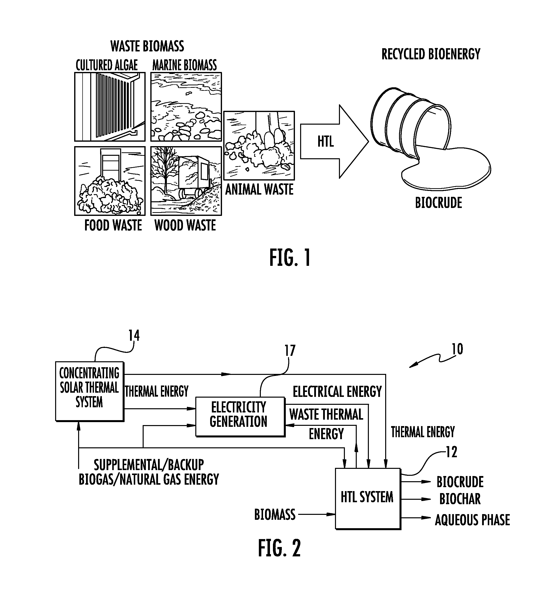
[0031]In addition, other implementations convert biowaste, such as municipal biosolids and grease and food waste, to bi...


PUM


Abstract

Systems and processes of providing novel thermal energy sources for hydrothermal liquefaction (HTL) reactors are described herein. According to various implementations, the systems and processes use concentrated solar thermal energy from a focused high-energy beam to provide sufficient energy for driving the HTL biomass-to-biocrude process. In addition, other implementations convert biowaste, such as municipal biosolids and grease and food waste, to biocrude using anaerobic digesters, and a portion of the biogas generated by the digesters is used to produce the thermal and / or electrical energy used in the HTL reactor for the biomass-to-biocrude process. Furthermore, alternative implementations may include a hybrid system that uses biogas and solar radiation to provide sufficient thermal energy for the HTL reactor.

Description

RELATED APPLICATIONS[0001]This application claims priority to U.S. Provisional Patent Application No. 61 / 886,463 filed Oct. 3, 2013 and entitled “Systems and Methods for Converting Biomass to Biocrude via Hydrothermal Liquefaction,” the content of which is herein incorporated by reference in its entirety.BACKGROUND[0002]The Energy Independence and Securities Act of 2007 (EISA) established mandatory Renewable Fuel Standards (RFS) that require an increase from 9 billion gallons in 2008 to a minimum of 36 billion gallons of renewable fuels to be blended in transportation fuels sold in the US by 2022. Today, we face a challenge in meeting these mandates partly because of the energy requirements of generating advanced biofuels as well as sourcing an adequate supply of reliable feedstocks.[0003]To date, the microalgae-to-renewable fuel pathway has focused on the generation of lipids within the microalgae, followed by the extraction and conversion of those lipids to biodiesel. The process ...

Claims


Application Information

Patent Timeline
IPC IPC(8): C10G1/02F23G5/027C12P1/00F24S23/71F24S23/74
CPCC10G1/02F23G5/027C12P1/00F23G2900/50803Y02P20/129Y02P30/20C12M43/08C12P5/023C12M21/02C12M21/04C12M21/12C12M43/00C10G2300/1003C10G2300/1007C10G2300/1011C10G2300/1014C10G2300/1018Y02E20/12Y02W10/37C10G1/00C10G1/065Y02E50/10Y02E50/30Y02P20/133C10G3/40C10G3/52
Inventor BERBEROGLU, HALILCONNELLY, RHYKKA L.ANTHONY, JOEYBOND, CODY
Owner BOARD OF RGT THE UNIV OF TEXAS SYST
Learn More