Statically stable walking machine and power system therefor

a walking machine and statically stable technology, applied in the field of walking machines, can solve the problems of low payload vs. vehicle mass ratio, general suffering of statically stable walking machines, and high power consumption, so as to increase the capabilities of the machine, ensure the stability, and increase the locomotion performance

Active Publication Date: 2015-04-16
RISKAS BRIAN
View PDF12 Cites 14 Cited by
  • Summary
  • Abstract
  • Description
  • Claims
  • Application Information

AI Technical Summary

Benefits of technology

[0028]Once ground contact is made (either through arrival at the commanded position or through ground contact sensor reading), the leg microcontroller queries the positions of each joint and then reports the new foot member position back to the main controller, along with a confirmation of foot member contact with the ground. The main controller can then use these coordinates when generating new commands for each of the legs, based on the input from the operator. Because the main controller has confirmation of which legs are on the ground at any one time, static stability can be ensured without active participation by the operator.
[0029]It will be appreciated that more sensors can be added as desired to increase the capabilities of the machine, and add additional behaviors to increase the locomotion performance. It will be appreciated that in a preferred embodiment, each component (e.g., leg member) is controlled independently of the other components via the components own microcontroller. However, it will be further appreciated that each microcontroller may control only a single EHA or multiple EHAs.

Problems solved by technology

These statically stable walking machines generally suffer from a number of short-comings: low payload vs. vehicle mass ratio, high power consumption when under low load, and general reliability and maintenance issues that arise due to having closely packaged hydraulic circuits.
Furthermore, walking machines with traditional hydraulic systems need constant system pressure to maintain position, which consumes a significant amount of power.

Method used


Image

  • Statically stable walking machine and power system therefor
  • Statically stable walking machine and power system therefor
  • Statically stable walking machine and power system therefor

Examples


Embodiment Construction

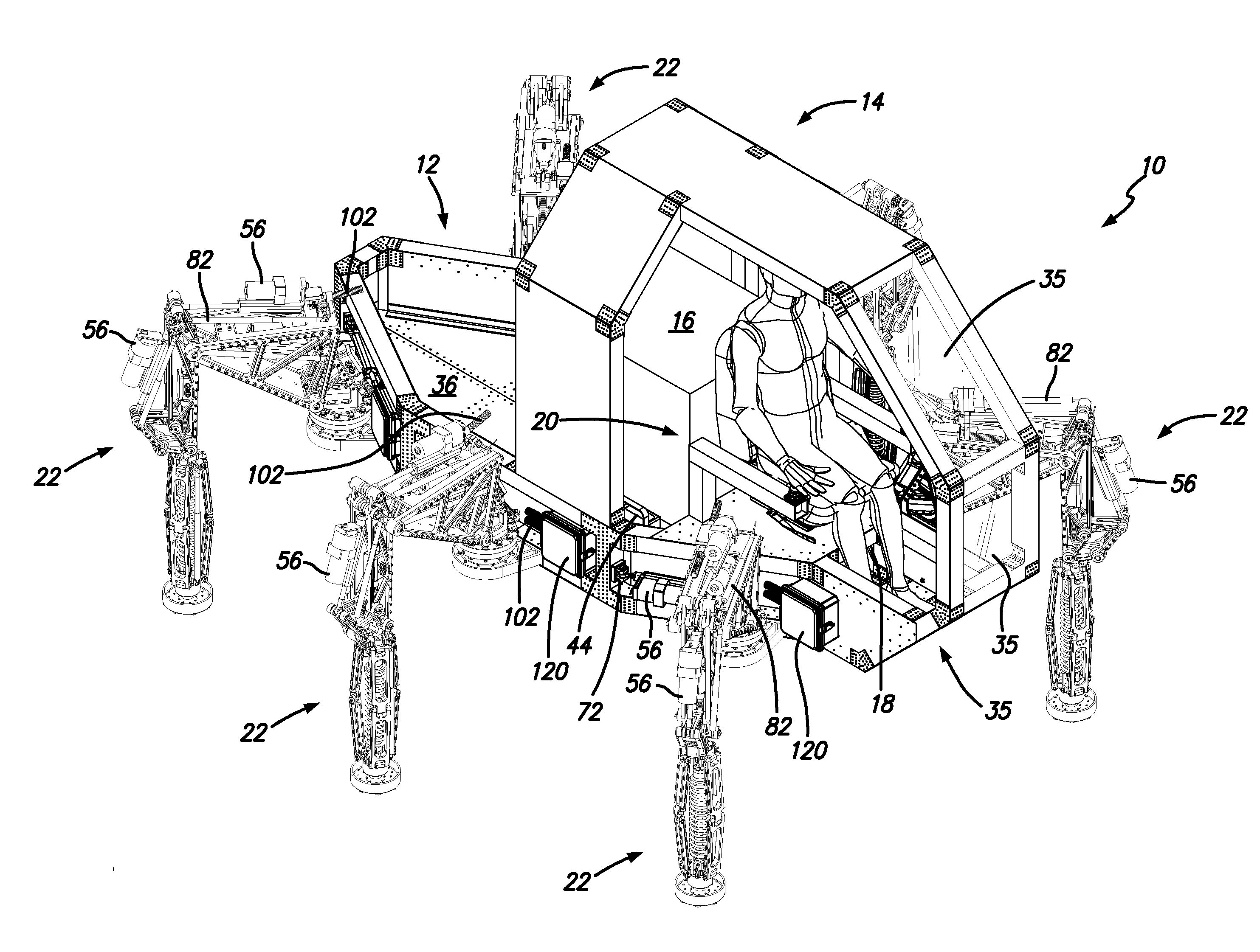
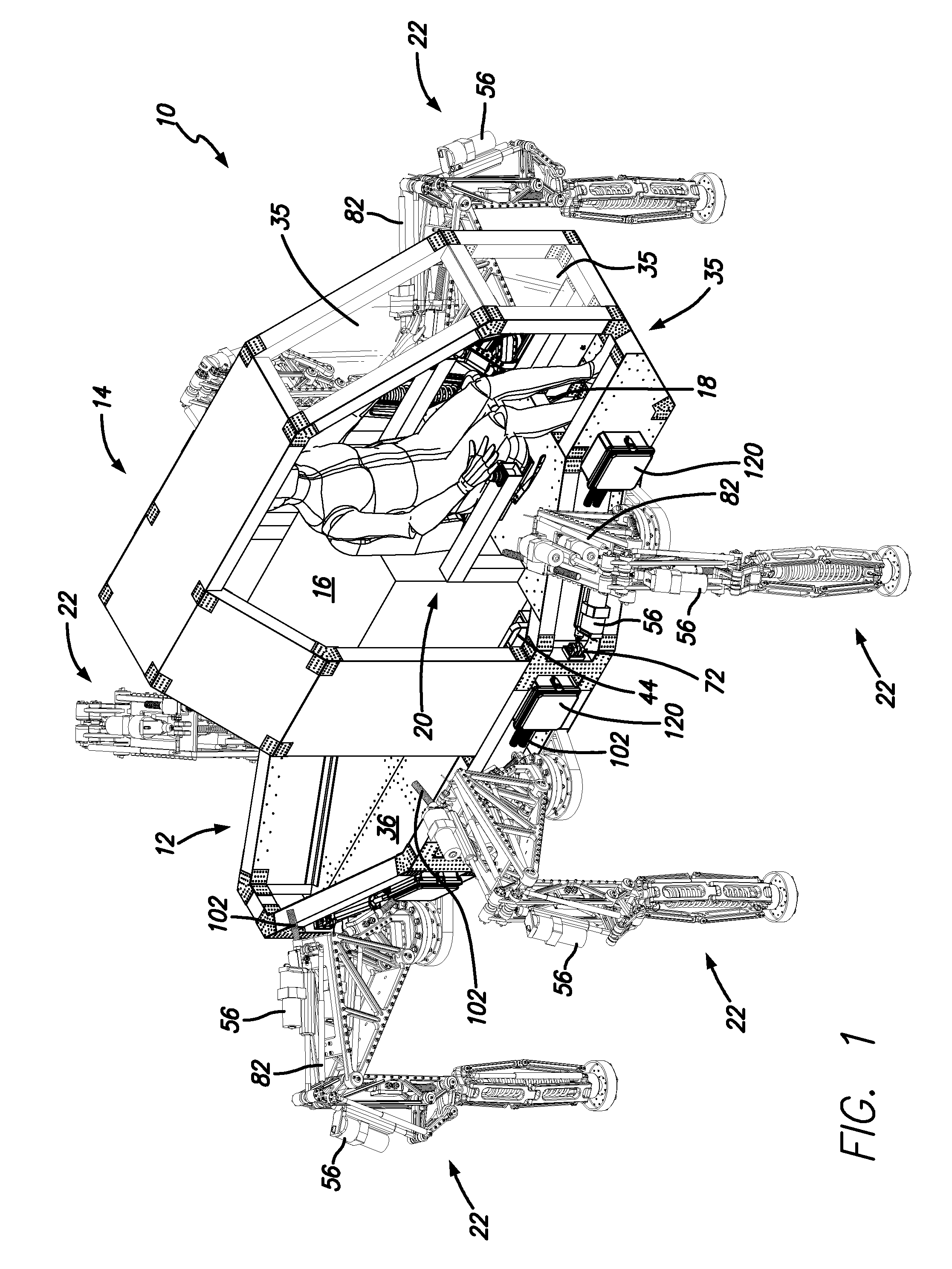
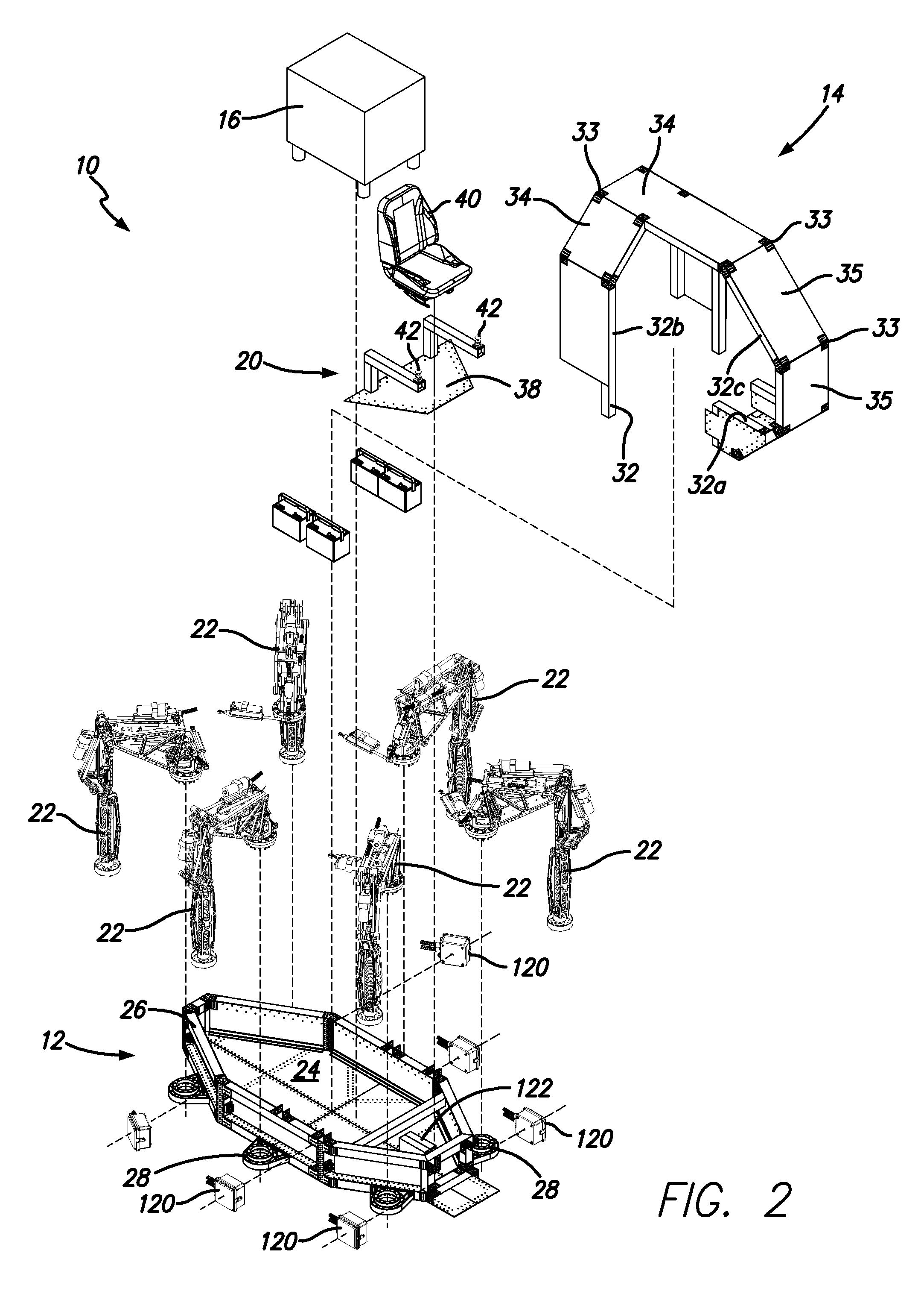
[0005]In accordance with a first aspect of the present invention there is provided a walking machine that includes a chassis with an operator interface, a main controller in data communication with the operator interface, at least two leg members operatively connected to the chassis, and a power system in data communication and electrical communication with the main controller. Each leg member includes a leg control system that includes a leg microcontroller in data communication with the main controller and at least a first electro hydrostatic actuator in electrical communication with the leg microcontroller. The power system includes an electrical generator, power supply electronics in electrical communication with the electrical generator, an electrical storage medium in electrical communication with the electrical generator and in parallel with the power supply electronics, and an electrical power bus for distributing power from the power system to the leg control systems.

[0006]...


PUM


Abstract

A walking machine that includes a chassis with an operator interface, a main controller in data communication with the operator interface, at least two leg members operatively connected to the chassis, and a power system in data communication and electrical communication with the main controller. Each leg member includes a leg control system that includes a leg microcontroller in data communication with the main controller and at least a first electro hydrostatic actuator in electrical communication with the leg microcontroller. The power system includes an electrical generator, power supply electronics in electrical communication with the electrical generator, an electrical storage medium in electrical communication with the electrical generator and in parallel with the power supply electronics, and an electrical power bus for distributing power from the power system to the leg control systems.

Description

CROSS REFERENCE TO RELATED APPLICATIONS[0001]This application claims the benefit of U.S. Provisional Application No. 61 / 890,508, filed Oct. 14, 2013 and U.S. Provisional Application No. 61 / 900,242, filed Nov. 5, 2013, which are both herein incorporated by reference in their entireties.FIELD OF THE INVENTION[0002]The present invention relates to a walking machine, and more particularly to a powertrain or system for a statically stable walking machine.BACKGROUND OF THE INVENTION[0003]According to a study conducted by the US Army in 1967, approximately half of the world's landmass or terrain is inaccessible to wheeled or tracked vehicles. However, legged animals and people generally have no issues accessing these areas. Accordingly, walking machines have been developed for accessing such terrain.[0004]Many previous walking machines possess the same system level hydraulic architecture. These machines use a prime mover (usually an internal combustion engine) to drive a hydraulic pump tha...

Claims


Application Information

Patent Timeline
Patent Type & Authority Applications(United States)
IPC IPC(8): B62D57/032F15B21/08
CPCB62D57/032F15B21/085E02F3/42E02F9/2075E02F9/2095E02F9/2271F15B15/18F15B18/00
Inventor RISKAS, BRIAN
Owner RISKAS BRIAN
Why Eureka
Try Eureka