Supercharge Your Innovation With Domain-Expert AI Agents!

Systems and methods for implementing a unique variable stacking surface for set compiling in image forming devices

a technology of image forming device and stacking surface, which is applied in the direction of thin material processing, article separation, article delivery, etc., can solve the problems of particular complexity in the processing of documents responsive to directed print jobs, and achieves high speed, easy implementation, and reduced overall mechanical movement

Active Publication Date: 2015-04-16
XEROX CORP
View PDF10 Cites 1 Cited by
  • Summary
  • Abstract
  • Description
  • Claims
  • Application Information

AI Technical Summary

Benefits of technology

The patent text outlines a problem of image receiving media substrates handling difficulties in image forming devices, especially with high-speed document preparation requirements. The text proposes optimizing movement of these substrates by reducing and slowing down the overall mechanical movement of certain components in the vertical image receiving media transport paths. The text also mentions innovating in vertical converter components to optimize the configuration of connector trays and make use of the unique aspects of auger-based vertical movement. The patent text describes the modification of connector trays to cooperate with the shape of the augers and add a receiver surface to accommodate local elevations or different thicknesses of the substrates. These modifications enable the effective mechanical flattening of the top surface of the substrates, which helps improve image receiving media substrate handling in image forming devices and systems.

Problems solved by technology

Manipulation of the individual image receiving media substrates, or of the sets of image receiving media substrates, at that point in the processing of the documents responsive to the directed print job can be particularly intricate.

Method used


Image

  • Systems and methods for implementing a unique variable stacking surface for set compiling in image forming devices
  • Systems and methods for implementing a unique variable stacking surface for set compiling in image forming devices
  • Systems and methods for implementing a unique variable stacking surface for set compiling in image forming devices

Examples


Embodiment Construction

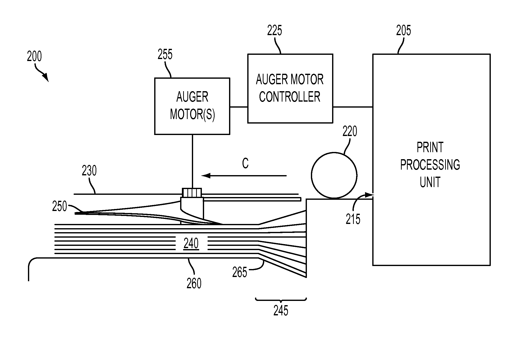
[0014]Both of the above-described drop functions will often tend to introduce variation in set registration in the first individual sheet drop stage and the set-to-set (stack) registration in the second drop stage. U.S. patent application Ser. No. 14 / 039,045, entitled “Systems and Methods For Implementing An Auger-Based Transport Mechanism For Vertical Transport Of Image Receiving Media In Image Forming Systems,” to Herrmann, the disclosure of which is hereby incorporated by reference herein in its entirety describes an auger-based vertical transport system for uniquely addressing shortfalls in conventional vertical transport components.

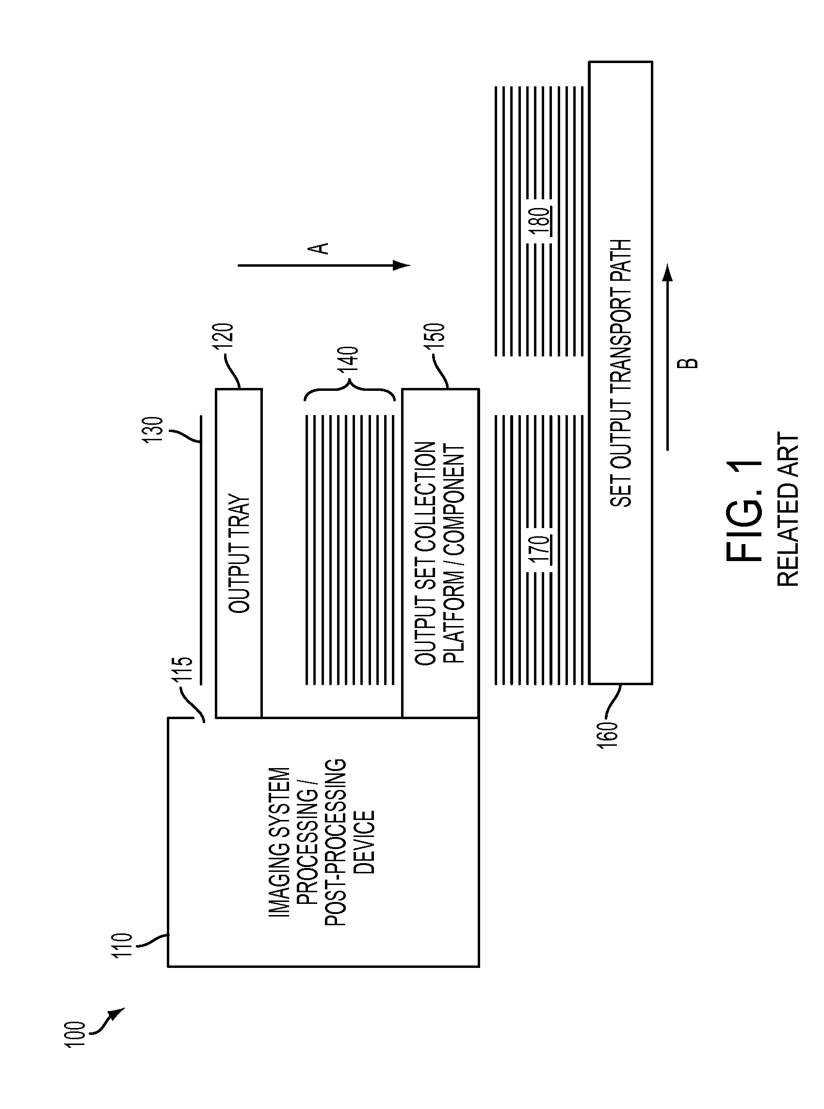
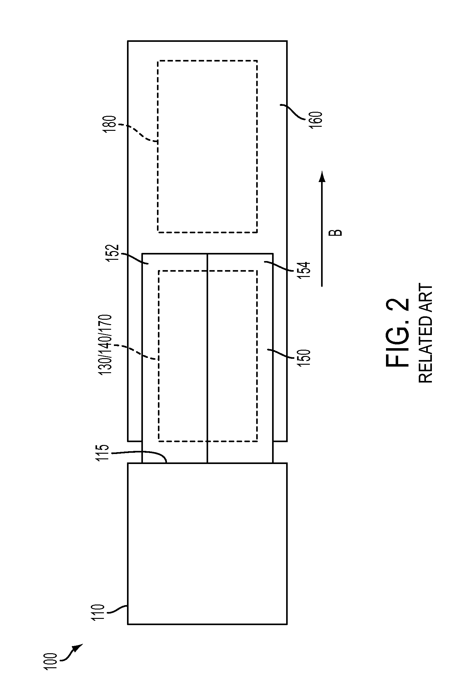
[0015]Difficulties may arise in the compiling of output collections of individual image receiving media substrates, and moreover in the collection of multiple sets of image receiving media substrates in certain currently-fielded image forming devices and image forming systems, particularly for use in an office environment. The image forming and finis...


PUM

PropertyMeasurementUnit
compressing forceaaaaaaaaaa
sizeaaaaaaaaaa
areasaaaaaaaaaa

Abstract

A system and method are provided for improving stack integrity for image receiving media substrates in a compiler tray in an image forming device by supplementing the structure of the compiler tray with a pair of auger components configured with a bottom surface that, in conjunction with a stepped support structure in the compiler tray, applies a mechanical leveling force to reduce or otherwise eliminate detrimental effects associated with substrate curl or uneven set build-up in the compiler tray. The vertical compiler components provide an accommodation for localized thickness build-up in compiled image receiving media substrates by one or more processing or post-processing steps. The auger components provide a mechanical pressing force that is intended to level a top surface of the compiled substrates with the configuration of the compiler tray providing the relief area necessary for the accommodation.

Description

[0001]This application is related to U.S. patent application Ser. No. 14 / 039,045, entitled “Systems and Methods For Implementing An Auger-Based Transport Mechanism For Vertical Transport Of Image Receiving Media In Image Forming Systems,” to Herrmann, filed on Sep. 27, 2013, and U.S. patent application No. [Attorney Docket No. 056-0585], entitled “Systems And Methods For Implementing A Unique Planar Stacking Surface For Set Compiling In Image Forming Devices,” filed on Oct. 15, 2013, a same day as this application. The disclosures of the above-identified references are hereby incorporated by reference herein in their entireties.BACKGROUND[0002]1. Field of Disclosed Subject Matter[0003]This disclosure relates to systems and methods for improving stack integrity for image receiving media substrates in a compiler tray in an image forming device by supplementing the structure of the compiler tray with a pair of auger components configured with a bottom surface that, in conjunction with ...

Claims


Application Information

Patent Timeline
Patent Type & Authority Applications(United States)
IPC IPC(8): B65H3/28B65H3/52B65H1/04
CPCB65H3/28B65H1/04B65H3/52B65H31/26B65H2301/4212B65H2405/1116B65H2701/18292B65H2801/06B65H29/42B65H2301/4223B65H2404/663B65H2405/1111
Inventor STOJANOVSKI, BILLY T.CURRY, GERALD ROYHATCH, THOMAS CROFTONLINDER, MICHAEL J.UTHMAN, TODD MAURICEFESS, DONALD R.
Owner XEROX CORP
Features
  • R&D
  • Intellectual Property
  • Life Sciences
  • Materials
  • Tech Scout
  • Unparalleled Data Quality
  • Higher Quality Content
  • 60% Fewer Hallucinations
Learn More