Lens, optical imaging lens set and method for forming a lens

Inactive Publication Date: 2015-04-16
GENIUS ELECTRONICS OPTICAL CO LTD
View PDF8 Cites 42 Cited by
  • Summary
  • Abstract
  • Description
  • Claims
  • Application Information

AI Technical Summary

Benefits of technology

[0029]According to the lens and the optical imaging lens set including the lens of the present invention, the opaque layer disposed on the extending part of the lens body can absorb or reflect scattered light effectively, which prevents scattered light from irradiating on the image plane. Flares are thereby eliminated, which increases the image quality. In addition, since the opaque layer is only formed on the extending part, but not formed on the optical effective part, the emitted light will not be blocked by the opaque layer.
[0030]Since the opaque layer has the ability to eliminate scattered light, the number of gaskets can be decreased. In

Problems solved by technology

The manufacturing process for forming the gasket becomes more difficult.
Moreover, the gasket can only be formed on a flat lens surface

Method used


Image

  • Lens, optical imaging lens set and method for forming a lens
  • Lens, optical imaging lens set and method for forming a lens
  • Lens, optical imaging lens set and method for forming a lens

Examples


Example

Example 1

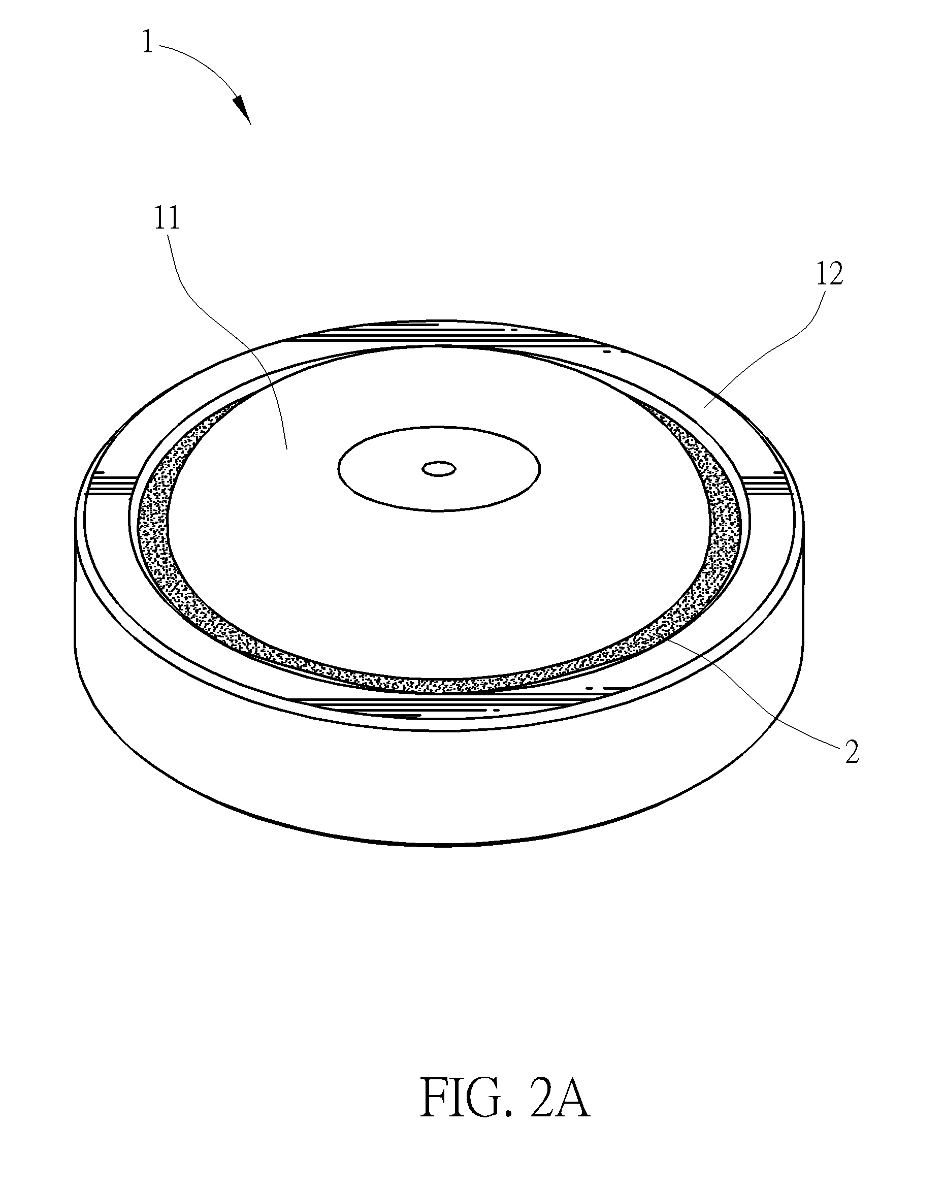
[0055]Please refer to FIGS. 2A and 2B, which illustrate a lens, comprising: a lens body 1, including an optical effective part 11 and an extending part 12, wherein the optical effective part 11 is the region A1 that allows an ideal image light to pass through, the extending part 12 is a ring-shaped structure surrounding the periphery region of the optical effective part 11 and extending outward from the periphery region of the optical effective part 11. Ideally, an image light will not pass through the extending part 12. The lens body 1 has an annular surface B1 facing an object-side and disposed on the extending part 12, and further has an annular surface B2 facing an image-side and disposed on the extending part 12. In other words, the lens body 1 has two surfaces, wherein one faces the object-side, and the other faces the image-side. The extending part 12 also has two annular surfaces: annular surface B1 and annular surface B2, which are disposed on two sides of the exte...

Example

Example 2

[0057]Refer to FIG. 3. The example is substantially similar to example 1. The difference between these two examples is that, in this example, the opaque layer 2 not only can be formed on the annular surface B2, but also can be formed on the annular surface B1. The materials of the opaque layer, and the method for forming the opaque layer on the annular surface B1 and annular surface B2 of the extending part 12 are similar to those described in example 1, and will be omitted here.

Example

Example 3

[0058]Refer to FIG. 4. The example is substantially similar to example 1. The difference between these two examples is that, in this example, an anti-reflective layer (transmittance improving layer) 3 covers the surface of the optical effective part 11 and the surface of the extending part 12 of the lens body 1, so as to improve the optical transmittance of the lens body 1. In this example, the opaque layer 2 is formed on the anti-reflective layer 3 which covers the annular surface B2.


PUM

PropertyMeasurementUnit
Diameteraaaaaaaaaa
Reflectionaaaaaaaaaa
Opacityaaaaaaaaaa

Abstract

A lens includes: a lens body, including an optical effective part and an extending part, wherein the extending part surrounds a periphery region of the optical effective part, and the extending part has at least one annular surface; and an opaque layer, disposed on the annular surface of the extending part. An optical imaging lens set includes a barrel; and an imaging component is disposed in the barrel. The imaging component includes at least one lens arranged along an optical axis, and one of these lenses is the lens mentioned above. A method for forming a lens forms the opaque layer on the annular surface of the extending part through a stamping method or through an evaporation method.

Description

CROSS REFERENCE TO RELATED APPLICATION[0001]This application claims priority from P.R.C. Patent Application No. 201310483867.2, filed on Oct. 16, 2013 the contents of which are incorporated by reference in their entirety.BACKGROUND OF THE INVENTION[0002]1. Field of the Invention[0003]The present invention relates to optics devices manufacturing, and more particularly, to a lens, an optical imaging lens set and a method for forming the lens.[0004]2. Description of the Prior Art[0005]A conventional optical imaging lens set is shown in FIG. 1. The optical imaging lens set includes a barrel, a plurality of lenses and a plurality of gaskets, wherein the gasket is either disposed between the barrel and the lens, or disposed between two adjacent lenses. The gasket is made of opaque and anti-reflective materials. When the light passes through the lens and forms an image on an image plane, the light can be reflected or absorbed by the gasket, which prevents the scattered light from irradiati...

Claims


Application Information

Patent Timeline
IPC IPC(8): G02B1/11G02B7/02
CPCG02B1/11G02B7/02G02B7/021
Inventor CHEN, SHEN-CHIEH
Owner GENIUS ELECTRONICS OPTICAL CO LTD
Why Eureka
Try Eureka