
Electrical component remote temperature monitoring system and method

Active Publication Date: 2015-04-16
ROCKWELL AUTOMATION TECH
View PDF3 Cites 9 Cited by
  • Summary
  • Abstract
  • Description
  • Claims
  • Application Information

AI Technical Summary

Benefits of technology

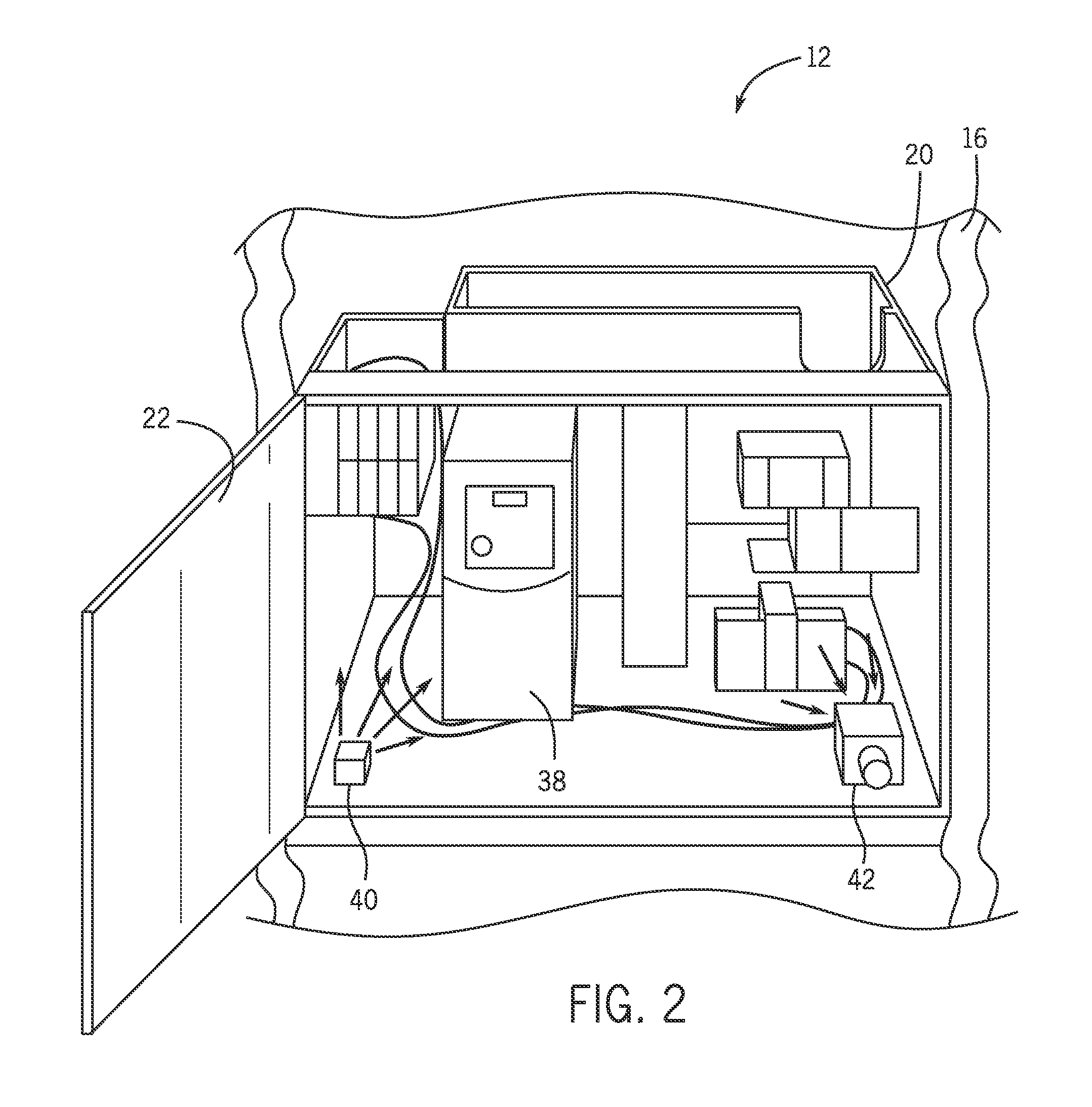
This patent describes a system and methods for remotely monitoring the inside of an electrical enclosure to detect hot spots and potential hot spots that may lead to overheating and damage. The monitoring system uses temperature-sensitive elements placed on or between the electrical components to determine the heating based on their change in appearance. A light source illuminates the temperature-sensitive elements and potential hot spots for better visibility. The monitoring system can communicate with computer equipment over a wireless network and alert an operator or notify them of a hot spot. The invention allows for real-time monitoring of electrical enclosures even when they are closed, and helps prevent damage to electrical equipment due to overheating.

Problems solved by technology

In some situations, electrical faults within the enclosure can cause sudden pressure increases and / or localized heating (e.g., hot spots).
For example, localized heating within the enclosure may damage wires, insulation, components, and even the structure of the enclosure.
Moreover, localized heating within the enclosure can lead to increased costs due to lost production time and system failures.
However, it is difficult to continuously (e.g., during operation) monitor a closed electrical enclosure for localized heating.
For example, it is difficult to examine the dark interior of a closed electrical enclosure to determine the location of the localized heating while the system is in normal operation mode.
Moreover, when a system is believed or known to be experiencing faults, considerable time may be involved in donning and doffing appropriate gear to open the enclosures for manual verification and servicing.
Heating that does not or that does not necessarily result in arcing is simply undetectable by such approaches.

Method used


Image

  • Electrical component remote temperature monitoring system and method
  • Electrical component remote temperature monitoring system and method
  • Electrical component remote temperature monitoring system and method

Examples


Embodiment Construction

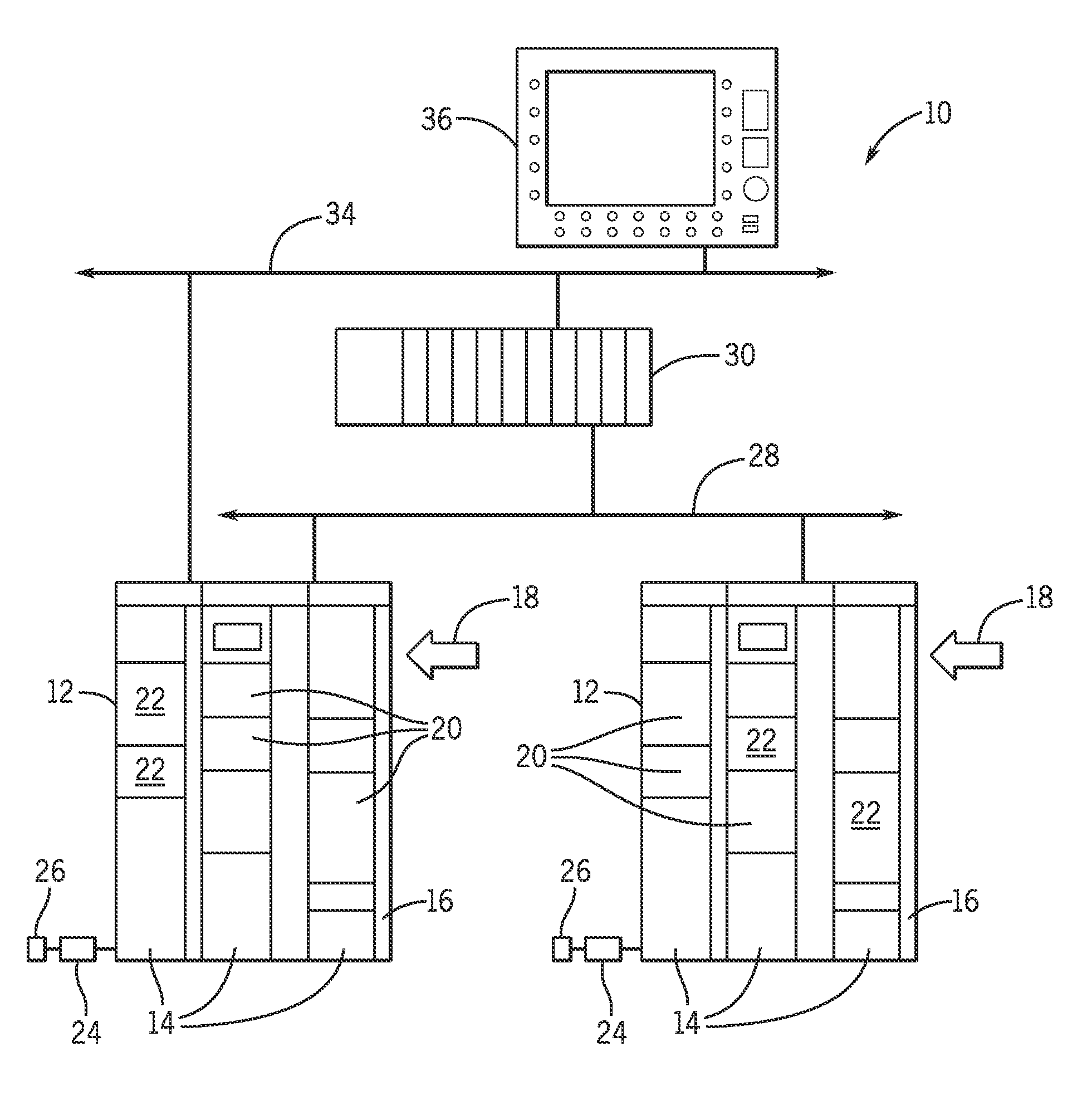
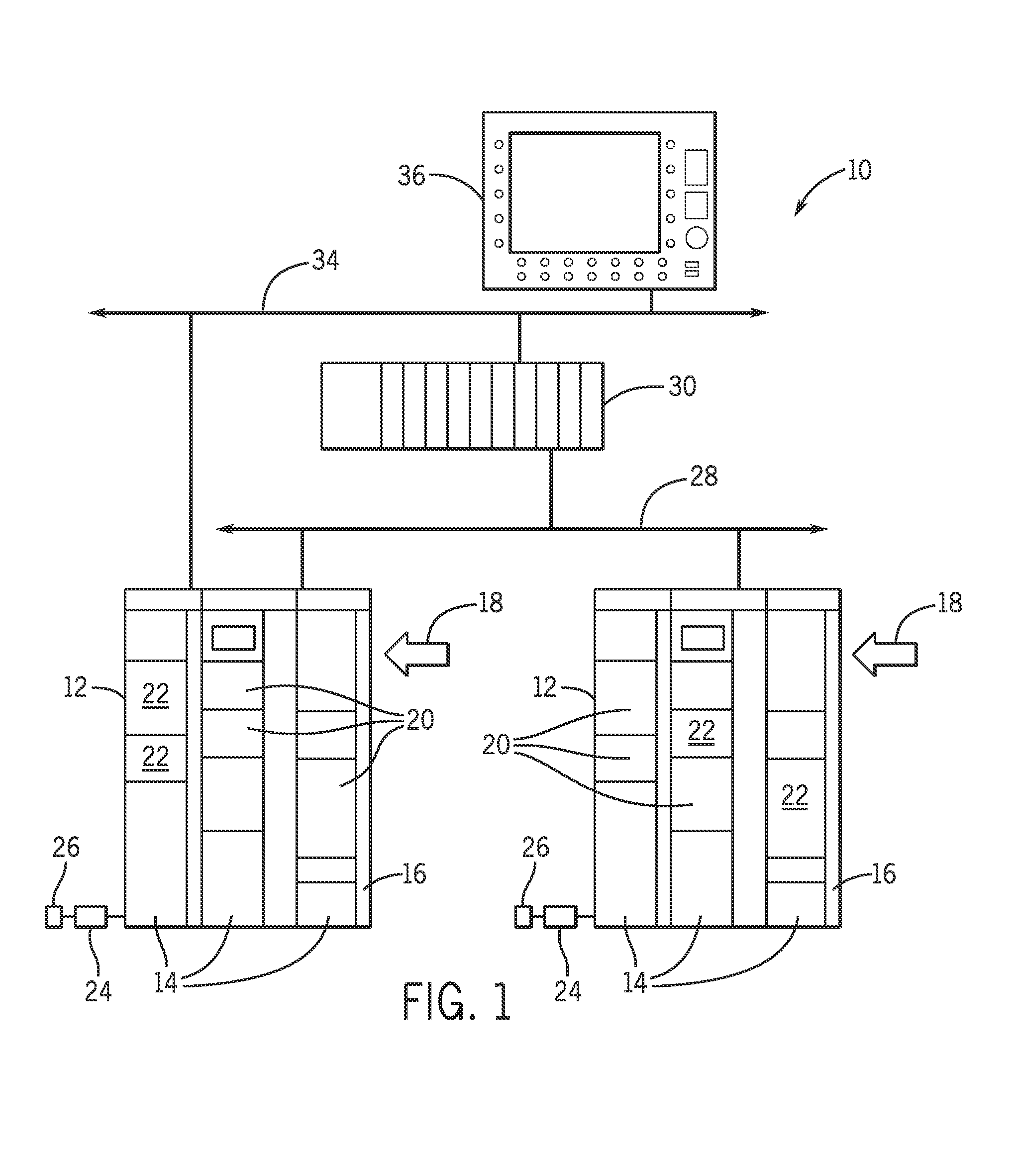
[0014]FIG. 1 is illustrates an embodiment of an automation system 10 having one or more electrical enclosures. In the depicted embodiments, the electrical enclosures may be one or more motor control centers (MCC) 12 used in various industrial and automation applications. Each MCC 12 comprises a cabinet having one or more sections 14 with one or more wireways 16 running alongside the sections 14. In certain embodiments, the wireways 16 may be dedicated for data, control power, load conductors, and so forth. In a typical application, power 18 is applied to the MCC 12 via three-phase power conductors. The power 18 may be coupled to a utility grid or may be drawn from local power generation equipment. While the present techniques are described with reference to MCCs, and particular components and circuits that they typically include, it should be borne in mind that the same techniques may be equally suitable for detecting hotspots in other settings, enclosures, applications, and so fort...


PUM


Abstract

The present techniques generally relate to a system and methods for remotely monitoring the interior of a closed electrical enclosure for localized heating (e.g., hot spots). In general, the monitoring system includes features designed to detect one or more hot spots within a dim or dark environment, determine the location of the hot spot within the enclosure, determine a temperature range of the hot spot, and / or notify (e.g., alarm or alert) an operator upon detection of the hot spot. The monitoring system may include one or more temperature sensitive elements configured to determine the heating of potential hot spots within the electrical enclosure. Further, the foregoing features may be designed to allow one or more electrical enclosures to remotely communicate with computer equipment (e.g., workstation or general purpose computers) over a wireless network.

Description

CROSS REFERENCE TO RELATED APPLICATIONS[0001]This application claims priority to Chinese Patent Application No. 201310274715.1 entitled “Electrical Component Remote Temperature Monitoring System and Method,” filed on Jul. 2, 2013, which is herein incorporated by reference.BACKGROUND[0002]The present invention relates generally to the field of electrical enclosures, such as enclosures for motor control centers used in industrial and commercial settings. More particularly, embodiments of the present invention relate to electrical enclosures designed with a remote temperature monitoring system.[0003]Electrical enclosures and cabinets can be used in a wide range of industrial and automation applications. The enclosures are configured to support electrical circuitry and electrical components therein, and to receive and send electrical power and data signals. For example, the enclosures can be employed to house various power electronics equipment, control circuits, motor drives, and so fo...

Claims


Application Information

Patent Timeline
IPC IPC(8): G01J5/08
CPCG01J5/0896G01J5/0066G01J5/0096G01J5/025G01J5/026G01J2005/0077G01K11/12
Inventor WEI, KUNQIAN, WEI
Owner ROCKWELL AUTOMATION TECH
Learn More