
Expanded beam array for fiber optics

a fiber optics and array technology, applied in the field of expanded beam multifiber connectors, can solve the problems of difficult manufacturing, high manufacturing cost, and complex molding equipment, and achieve the effect of reducing assembly time and labor

Inactive Publication Date: 2015-04-16
COMMSCOPE INC
View PDF13 Cites 58 Cited by
  • Summary
  • Abstract
  • Description
  • Claims
  • Application Information

AI Technical Summary

Benefits of technology

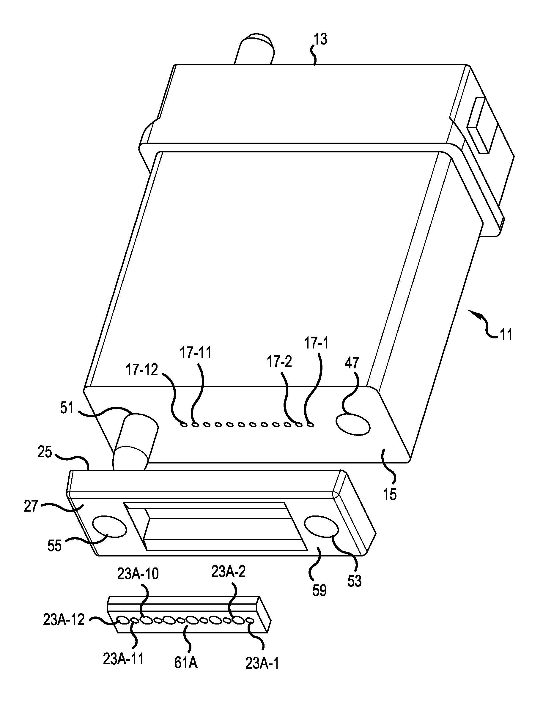
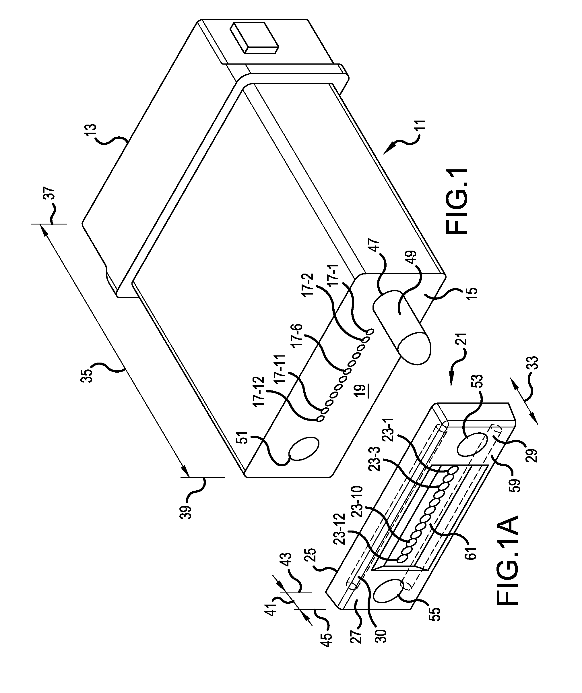
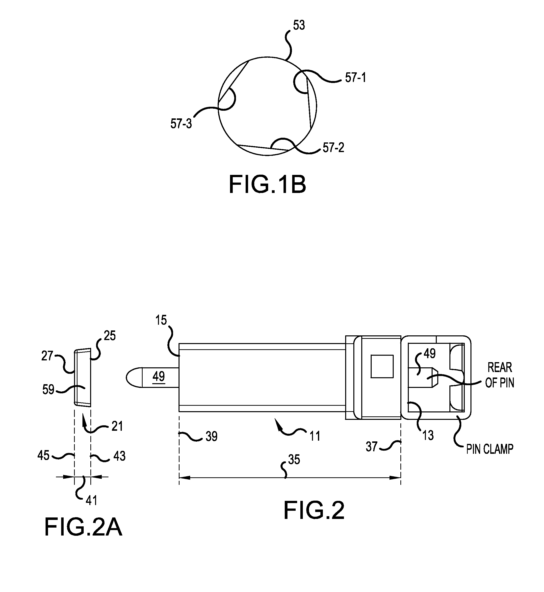
The present invention is about an improved design for an expanded beam multi-fiber connector. The connector has lenses that are part of the frame, which is made of a material suitable for the lenses, such as a polymer. The polymer used for the frame must be clean and free of fillers and contaminants to ensure consistent light transmission. The resulting connector is stronger than previous designs and has less expansion and contraction during temperature changes. The invention also provides the option of customizing the lenses for light transmission or reception to enhance the performance of the multi-fiber connector.

Problems solved by technology

For example, precision molding of the frame 102 can lead to manufacturing difficulties.
The molding equipment is rather complex with many moving elements, making it expensive to manufacture.
Further, the molding equipment requires added maintenance to keep tolerances adequate.
The signal attenuation through the lens material may lead to a drawback in that fiber cords employing connectors with the integrally molded lenses can only run from transceiver to transceiver.
Daisy-chaining fiber cords between transceivers could produce too much attenuation and cause a failure in the communication system.

Method used


Image

  • Expanded beam array for fiber optics
  • Expanded beam array for fiber optics
  • Expanded beam array for fiber optics

Examples


Embodiment Construction

[0041]The present invention now is described more fully hereinafter with reference to the accompanying drawings, in which embodiments of the invention are shown. This invention may, however, be embodied in many different forms and should not be construed as limited to the embodiments set forth herein; rather, these embodiments are provided so that this disclosure will be thorough and complete, and will fully convey the scope of the invention to those skilled in the art.

[0042]Like numbers refer to like elements throughout. In the figures, the thickness of certain lines, layers, components, elements or features may be exaggerated for clarity. Broken lines illustrate optional features or operations unless specified otherwise.

[0043]The terminology used herein is for the purpose of describing particular embodiments only and is not intended to be limiting of the invention. Unless otherwise defined, all terms (including technical and scientific terms) used herein have the same meaning as c...


PUM

PropertyMeasurementUnit
Distanceaaaaaaaaaa
Strengthaaaaaaaaaa
Coefficient of linear thermal expansionaaaaaaaaaa

Abstract

An expanded beam fiber optic array connector includes a ferrule holding ends of optical fibers in a first ordered array. A plurality of lenses packaged into a unitary structure, formed of an optical grade material, different than a material used to form the ferrule, is attached to the ferrule. The lenses are arranged into a second ordered array matching the first ordered array of the ends of the optical fibers. The lenses of the expanded beam connector associated with transmit channels can be constructed with a prescription geared specifically for transmitting light, whereas the lenses of the expanded beam connector associated with receive channels can be constructed with a prescription geared specifically for receiving light.

Description

[0001]This application claims the benefit of U.S. Provisional Application No. 61 / 891,348, filed Oct. 15, 2013, and U.S. Provisional Application No. 61 / 992,495, filed May 13, 2014, both of which are herein incorporated by reference.BACKGROUND OF THE INVENTION[0002]1. Field of the Invention[0003]The present invention relates to an expanded beam multi-fiber connector.[0004]2. Description of the Related Art[0005]An MTP / MPO (multi-fiber termination push-on / Multi-fiber Push On) or MT-RJ connector is known in the background art, such as in U.S. Pat. No. 6,880,980, which is incorporated herein by reference. Such connectors present one or more arrays of polished fiber ends at a front face of the MTP / MPO or MT-RJ connector, as shown in the figures of U.S. Pat. No. 6,880,980.[0006]Applicants' prior U.S. Pat. No. 8,393,804, which is incorporated herein by reference, demonstrated an advantage over the array type connectors having polished fiber ends. As shown in FIGS. 13 and 14, a multi-fiber co...

Claims


Application Information

Patent Timeline
IPC IPC(8): G02B6/38
CPCG02B6/3853G02B6/3863G02B6/3834G02B6/325G02B6/3885
Inventor BUSHNELL, BRIAN K.NIELSON, JEFFREY D.LOWE, SCOTT L.
Owner COMMSCOPE INC
Learn More