Wire harness

a wire harness and wire technology, applied in the field of wire harnesses, can solve the problems of increasing the complexity of the shielding treatment, the complexity of the structure, and the time-consuming of shielding treatment, so as to reduce the influence of noise, simplify the structure relevant to shielding treatment, and reduce the effect of nois

Active Publication Date: 2015-04-23
YAZAKI CORP
View PDF10 Cites 9 Cited by
  • Summary
  • Abstract
  • Description
  • Claims
  • Application Information

AI Technical Summary

Benefits of technology

[0011]In the related art, since the structure becomes more complicated as the number of types of or the number of lead-out directions of conductive paths increases, work for the shielding treatment becomes more complicated. When the structure becomes complicated, flexibility in designing a circuit decreases.
[0013]The present invention is made in light of the problems, and an object of the present invention is to provide a wire harness in which it is possible to achieve the simplification of work, a reduction in man-hours, and an improvement in flexibility in designing a circuit, and it is possible to reduce the influence of noise on another conductive path which is assembled into the wire harness together with a high-voltage conductive path.
[0018]In the wire harness of (1), since the high-voltage conductive path has the shielding member, the high-voltage conductive path alone can prevent noise from leaking to the outside without the aid of the metal pipe. It is possible to reduce the influence of noise on the another conductive path that is assembled into the wire harness together with the high-voltage conductive path. For this reason, the another conductive path being an unshielded electric wire can be assembled into the wire harness together with the high-voltage conductive path. In the wire harness of (1), since the metal pipe is not used as the shielding member, it is possible to make a structure relevant to a shielding treatment simpler than that in the related art. Since the structure becomes simplified, it is possible to reduce the number of man-hours required for the shielding treatment. Further, since the structure becomes simplified, it is possible to improve flexibility in designing a circuit. As such, in the wire harness of (1), it is possible to achieve the simplification of work, a reduction in man-hours, and an improvement in flexibility in designing a circuit. It is possible to reduce the influence of noise on the another conductive path that is assembled into the wire harness together with the high-voltage conductive path.

Problems solved by technology

In the related art, since the structure for the shielding treatment using the first and second flexible shielding members is complicated, the shielding treatment takes man-hours.
The use of the metal pipe as a shielding member is one of the causes of complicating the structure for the shielding treatment.
In the related art, since the structure becomes more complicated as the number of types of or the number of lead-out directions of conductive paths increases, work for the shielding treatment becomes more complicated.
When the structure becomes complicated, flexibility in designing a circuit decreases.

Method used


Image

  • Wire harness
  • Wire harness
  • Wire harness

Examples


first embodiment

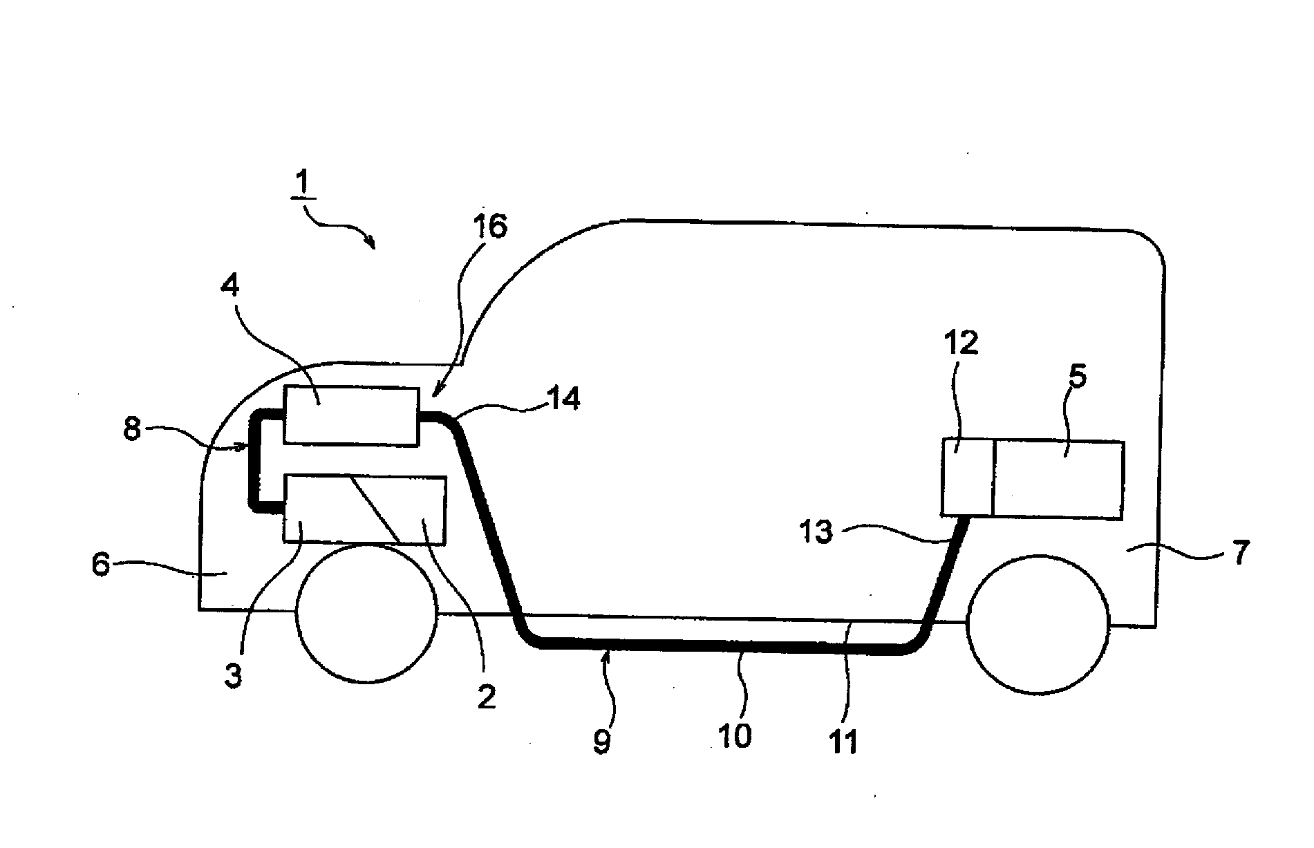
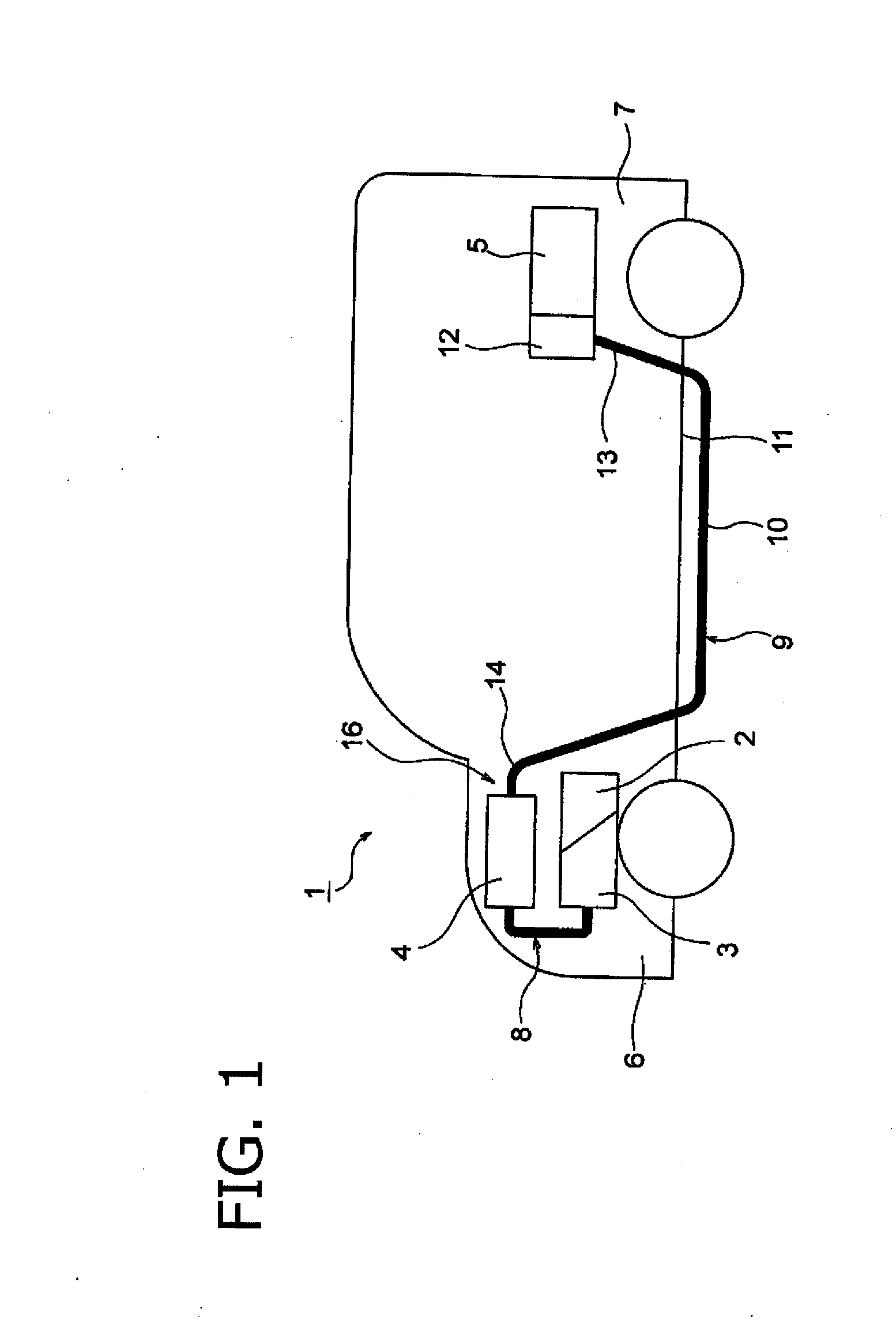
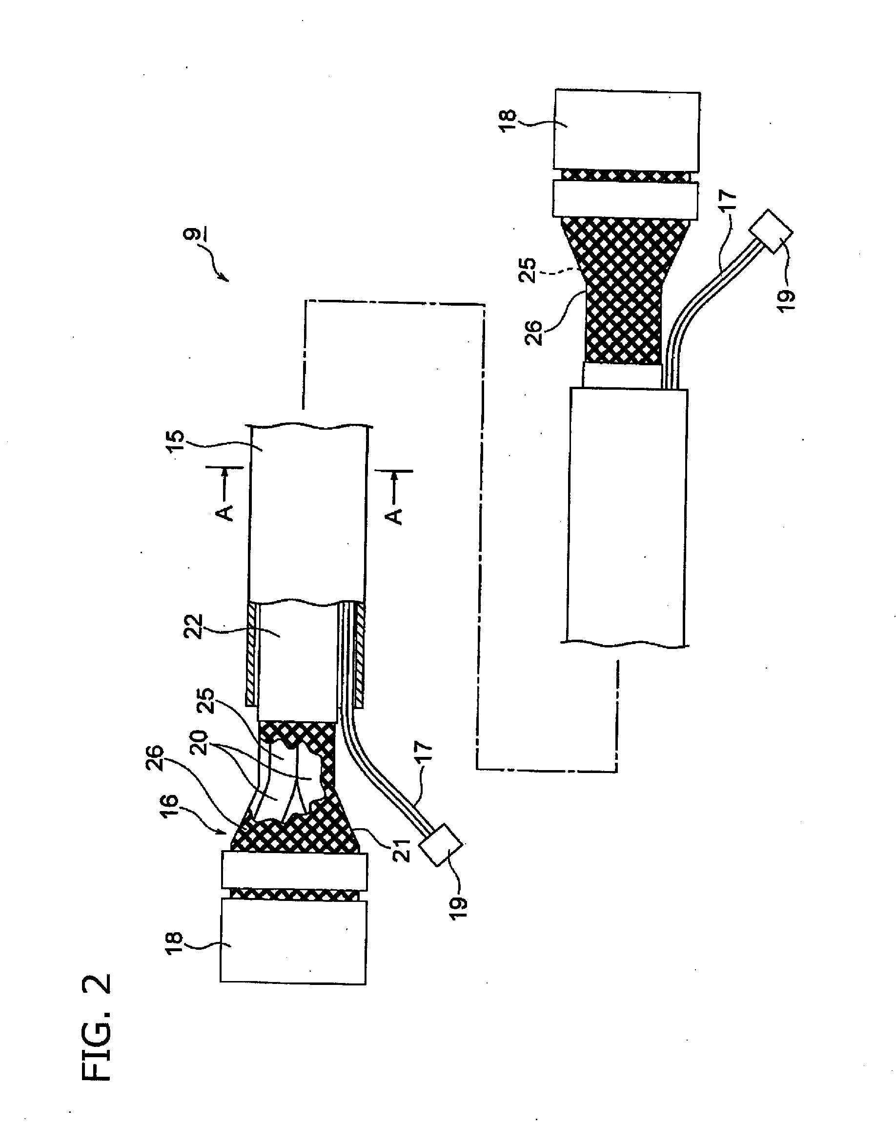
[0028]A wire harness according to a first embodiment of the present invention will be described with reference to FIGS. 1 to 4. FIG. 1 is a schematic view illustrating an arranged state of the wire harness according to the present invention. FIG. 2 is a view illustrating the configuration of the wire harness, FIG. 3A is a cross-sectional view taken along line A-A in FIG. 2, and FIG. 3B is a view illustrating a process of manufacturing the metal pipe. FIGS. 4A to 4C are views illustrating a process of manufacturing the wire harness.

[0029]In the following example, the present invention is applied to a wire harness arranged in a hybrid vehicle (may be an electric vehicle or a typical vehicle).

[0030]In FIG. 1, a reference sign 1 indicates a hybrid vehicle. The hybrid vehicle 1 is driven by a combination of two power from an engine 2 and a motor unit 3, and power is supplied to the motor unit 3 from a battery 5 (in other words, battery pack) via an inverter unit 4. In this example, the e...

second embodiment

[0058]Hereinafter, a second embodiment of a wire harness according to the present invention will be described with reference to FIG. 5. FIG. 5 is a view illustrating another example of the configuration of the wire harness.

[0059]In FIG. 5, a wire harness 31 includes a metal pipe used as an exterior member. The wire harness 31 further includes a high-voltage coaxial composite conductive path 33 (that is, a high-voltage conductive path) that is inserted into the metal pipe 32, and the low-voltage conductive paths 17 (that is, another conductive path) that are similarly inserted into the metal pipe 32, and are lined with the high-voltage coaxial composite conductive path 33. The wire harness 31 includes a high-voltage-side connecting portion (not illustrated) that is provided at an end of the high-voltage coaxial composite conductive path 33, and the low-voltage-side connecting portion 19 (refer to FIG. 2) that is provided at the ends of the low-voltage conductive paths 17.

[0060]The me...

third embodiment

[0069]Hereinafter, a third embodiment of a wire harness according to the present invention will be described with reference to FIG. 6. FIG. 6 is a view illustrating still another example of the configuration of the wire harness.

[0070]In FIG. 6, a wire harness 51 includes a metal pipe used as an exterior member. The wire harness 51 includes two high-voltage shielded electric wires 53 (that is, high-voltage conductive paths) that are inserted into the metal pipe 52, and the low-voltage conductive paths 17 (that is, another conductive path) that are similarly inserted into the metal pipe 52, and are lined with the high-voltage shielded electric wires 53. The wire harness includes a high-voltage-side connecting portion (not illustrated) that is provided at the ends of the high-voltage shielded electric wires 53, and the low-voltage-side connecting portion 19 that is provided at the ends of the low-voltage conductive paths 17.

[0071]The metal pipe 52 has a circular cross section, and exce...


PUM

PropertyMeasurementUnit
voltageaaaaaaaaaa
conductiveaaaaaaaaaa
thicknessaaaaaaaaaa

Abstract

A wire harness includes a metal pipe; a high-voltage conductive path; and another conductive path. Another conductive path is configured as an unshielded electric wire. The high-voltage conductive path includes a high-voltage circuit; a shielding member; and an insulating member.

Description

CROSS REFERENCE TO RELATED APPLICATIONS[0001]This application is a continuation of PCT application No. PCT / JP2013 / 069676, which was filed on July 19, 2013 based on Japanese Patent Application (No. 2012-160648) filed on Jul. 19, 2012, the contents of which are incorporated herein by reference.BACKGROUND OF THE INVENTION[0002]1. Field of the Invention[0003]One or more embodiments of the present invention relate to a wire harness that uses a metal pipe as an exterior member.[0004]2. Description of the Related Art[0005]Generally, a battery and an inverter unit in a hybrid vehicle or an electric vehicle are electrically connected to each other via a high-voltage (namely, for high-voltage) wire harness. The wire harness includes a conductive path and an exterior member that accommodates the conductive path.[0006]In JP-A-2006-310474, a conductive metal pipe is used as the exterior member. The metal pipe is also used as a shielding member for shielding the conductive path from electromagnet...

Claims


Application Information

Patent Timeline
Patent Type & Authority Applications(United States)
IPC IPC(8): H01B7/00
CPCH01B7/0045H01B7/0081B60R16/0215H02G3/0481H02G3/0487H01B9/04
Inventor ADACHI, HIDEOMIOZAKI, YOSHIAKI
Owner YAZAKI CORP
Why Eureka
Try Eureka