Multilayer printed circuit board

Inactive Publication Date: 2015-04-23
SAMSUNG ELECTRO MECHANICS CO LTD
View PDF4 Cites 21 Cited by
  • Summary
  • Abstract
  • Description
  • Claims
  • Application Information

AI Technical Summary

Benefits of technology

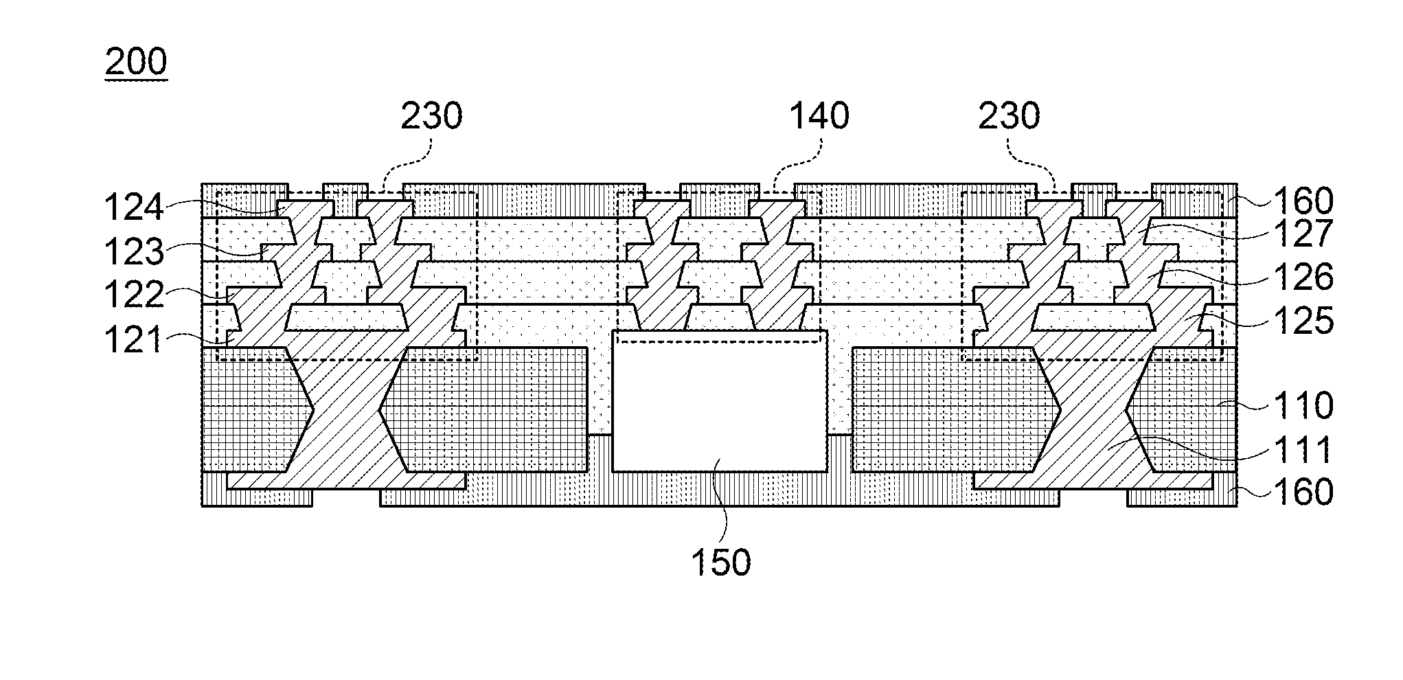
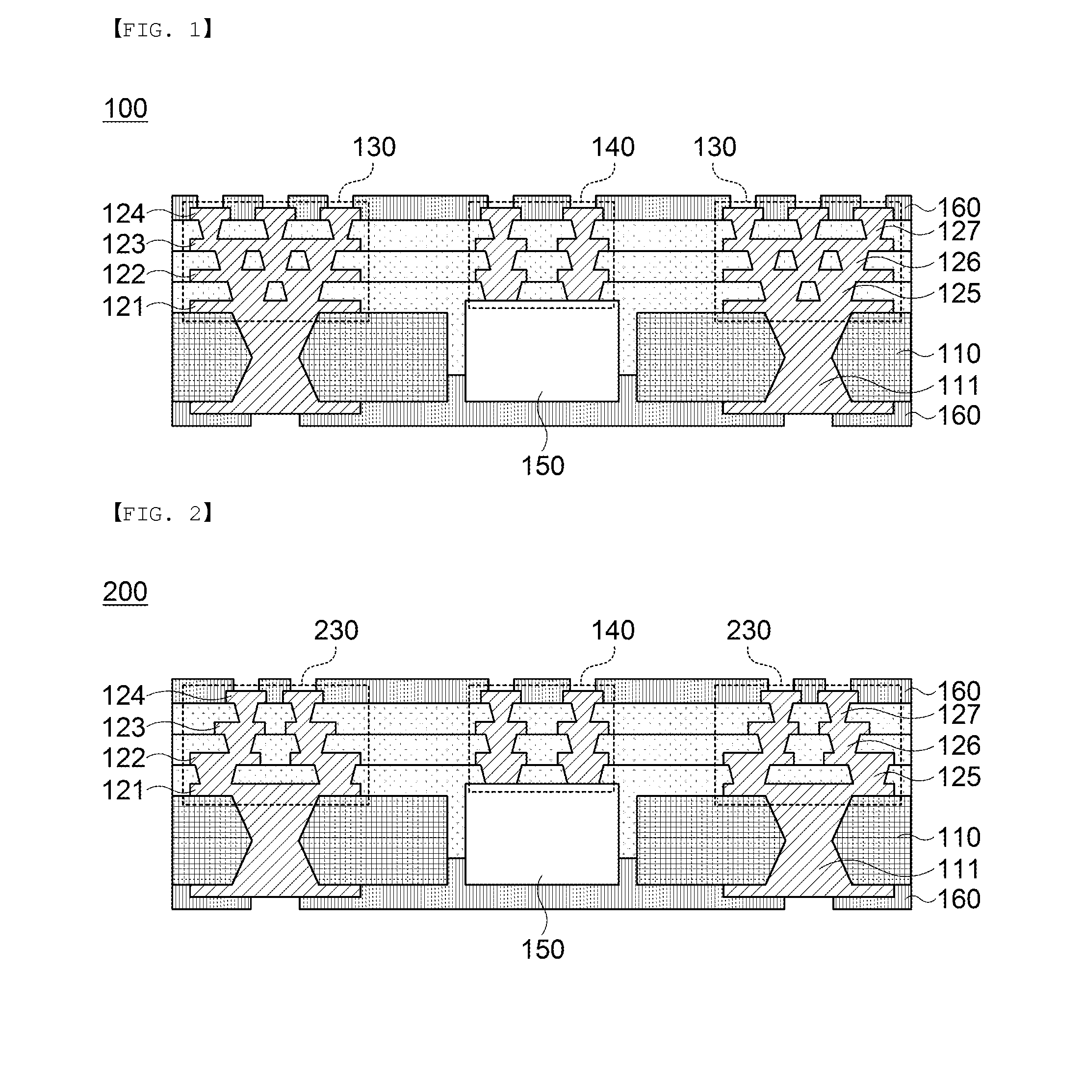
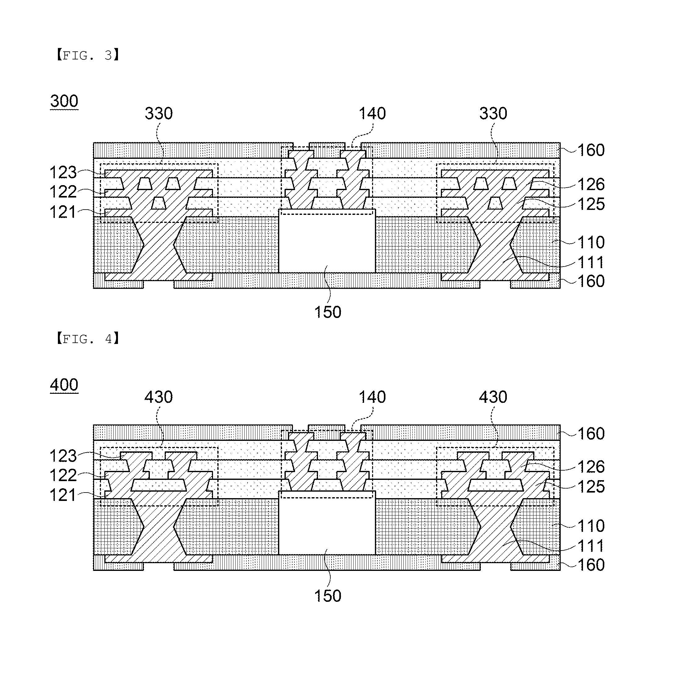
[0012]An object of the present invention is to provide a multilayer printed circuit board capable of intensively disposing vias at edge p

Problems solved by technology

In a general build-up package substrate, both surfaces thereof are built-up based on a core layer, and vias are formed in an outer portion having a chip mounted thereon, such that rigidity is not sufficient at the edge portion of the substrate, causing warpage in the substrate.
In ad

Method used


Image

  • Multilayer printed circuit board
  • Multilayer printed circuit board
  • Multilayer printed circuit board

Examples


Example

[0028]Various advantages and features of the present invention and methods accomplishing thereof will become apparent from the following description of embodiments with reference to the accompanying drawings. However, the present invention may be modified in many different forms and it should not be limited to the embodiments set forth herein. These embodiments may be provided so that this disclosure will be thorough and complete, and will fully convey the scope of the invention to those skilled in the art.

[0029]Terms used in the present specification are for explaining the embodiments rather than limiting the present invention. Unless explicitly described to the contrary, a singular form includes a plural form in the present specification. The word “comprise” and variations such as “comprises” or “comprising,” will be understood to imply the inclusion of stated constituents, steps, operations and / or elements but not the exclusion of any other constituents, steps, operations and / or ...


PUM


Abstract

Disclosed herein is a multilayer printed circuit board. The multilayer printed circuit board according to the present invention includes: a stack via stacked in an upper portion of a core layer; staggered vias formed at both sides of the stack via and stacked on the core layer; and a solder resist layer stacked in a lower portion of the core layer and stacked on an insulating film except for open regions of the stack via and the staggered vias, such that the plurality of vias formed in the staggered via may increase rigidity to prevent warpage of the multilayer printed circuit board from being generated.

Description

CROSS REFERENCE(S) TO RELATED APPLICATIONS[0001]This application claims the foreign priority benefit under 35 U.S.C. Section 119 of Korean Patent Application Serial No. 10-2013-0126060, entitled “Multilayer Printed Circuit Board” filed on Oct. 22, 2013, which is hereby incorporated by reference in its entirety into this application.BACKGROUND OF THE INVENTION[0002]1. Technical Field[0003]The present invention relates to a multilayer printed circuit board, and more particularly, to a multilayer printed circuit board preventing warpage during a process of manufacturing the printed circuit board.[0004]2. Description of the Related Art[0005]Recently, as electronic products become miniaturized, thinned, highly densified, and packaged, a printed circuit board has been fine-patterned in order to decrease a wiring density (for example, a width of the wiring or an interval between wirings).[0006]Accordingly, in order to implement the fine patterns and increase reliability and a designed dens...

Claims


Application Information

Patent Timeline
IPC IPC(8): H05K1/11H05K1/02H05K1/18
CPCH05K1/115H05K2201/096H05K1/0298H05K1/185H01L2224/04105H01L2924/3511H05K3/429H05K3/4644H05K3/4697H05K2201/09709H05K2201/0979H05K3/46
Inventor KIM, HYE JINNAM, HYO SEUNGMIN, TAE HONGKIM, SANG HOONCHO, SUK HYEONLEE, JUNG HAN
Owner SAMSUNG ELECTRO MECHANICS CO LTD
Why Eureka
Try Eureka