Multi-Axis Industrial Robot With Integrated Tool

a multi-axis industrial robot and tool technology, applied in the field of multi-axis industrial robots, can solve the problems of requiring a greater number of stops and a lower robot productivity, and achieve the effect of general improvement in its use efficiency

Inactive Publication Date: 2015-04-23
COMAU SPA
View PDF21 Cites 18 Cited by
  • Summary
  • Abstract
  • Description
  • Claims
  • Application Information

AI Technical Summary

Benefits of technology

[0004]An object of the present invention is to solve or improve on all the above problems in an optimum manner, by cr

Problems solved by technology

In robots of the type specified above, the harnessing of cables and pipes for the power supply and the fluid supply to the tool carried by the robot poses several problems.
Exposure of the cables to these agents often leads to greater and premature wear

Method used


Image

  • Multi-Axis Industrial Robot With Integrated Tool
  • Multi-Axis Industrial Robot With Integrated Tool
  • Multi-Axis Industrial Robot With Integrated Tool

Examples


first embodiment

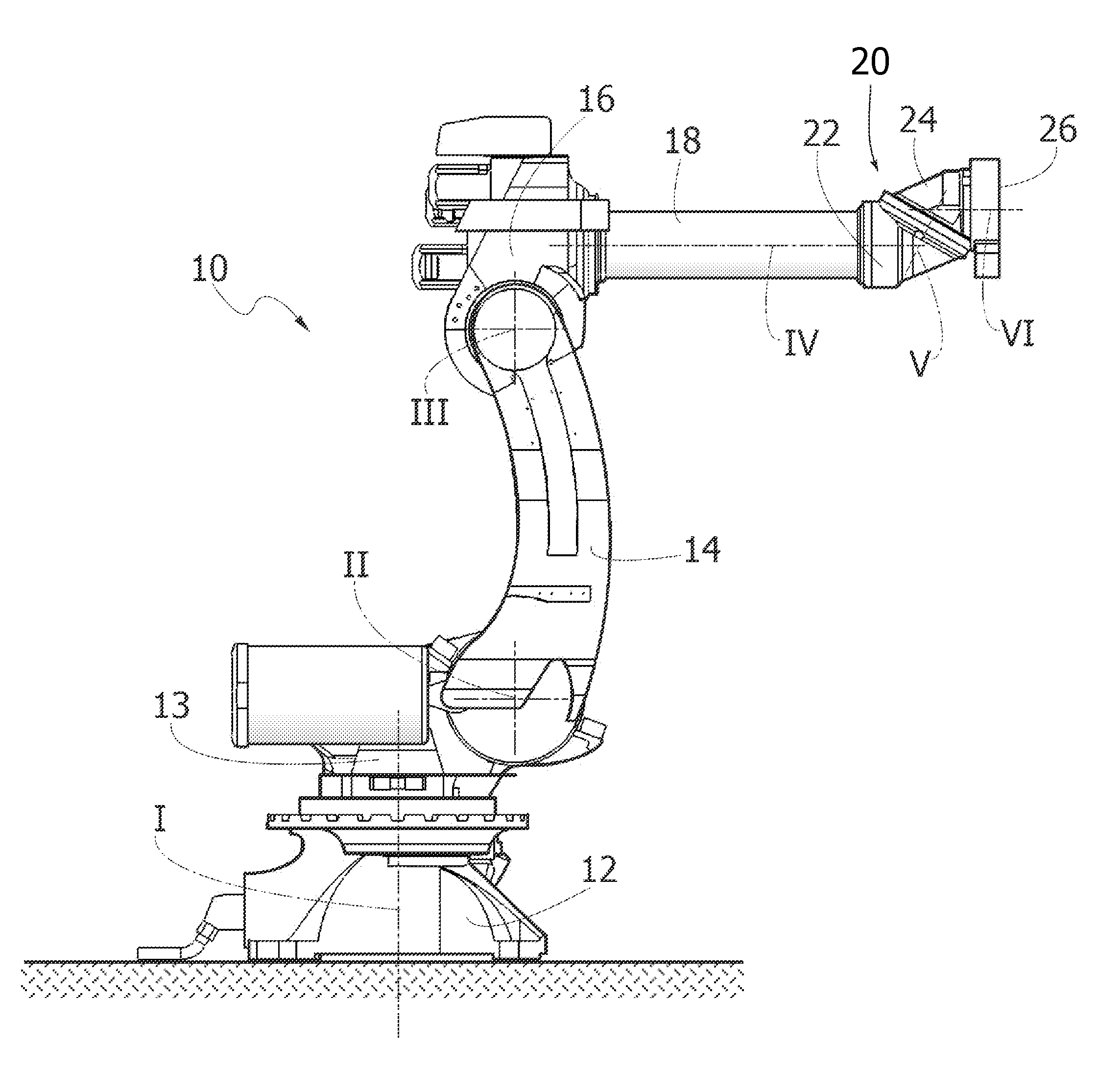
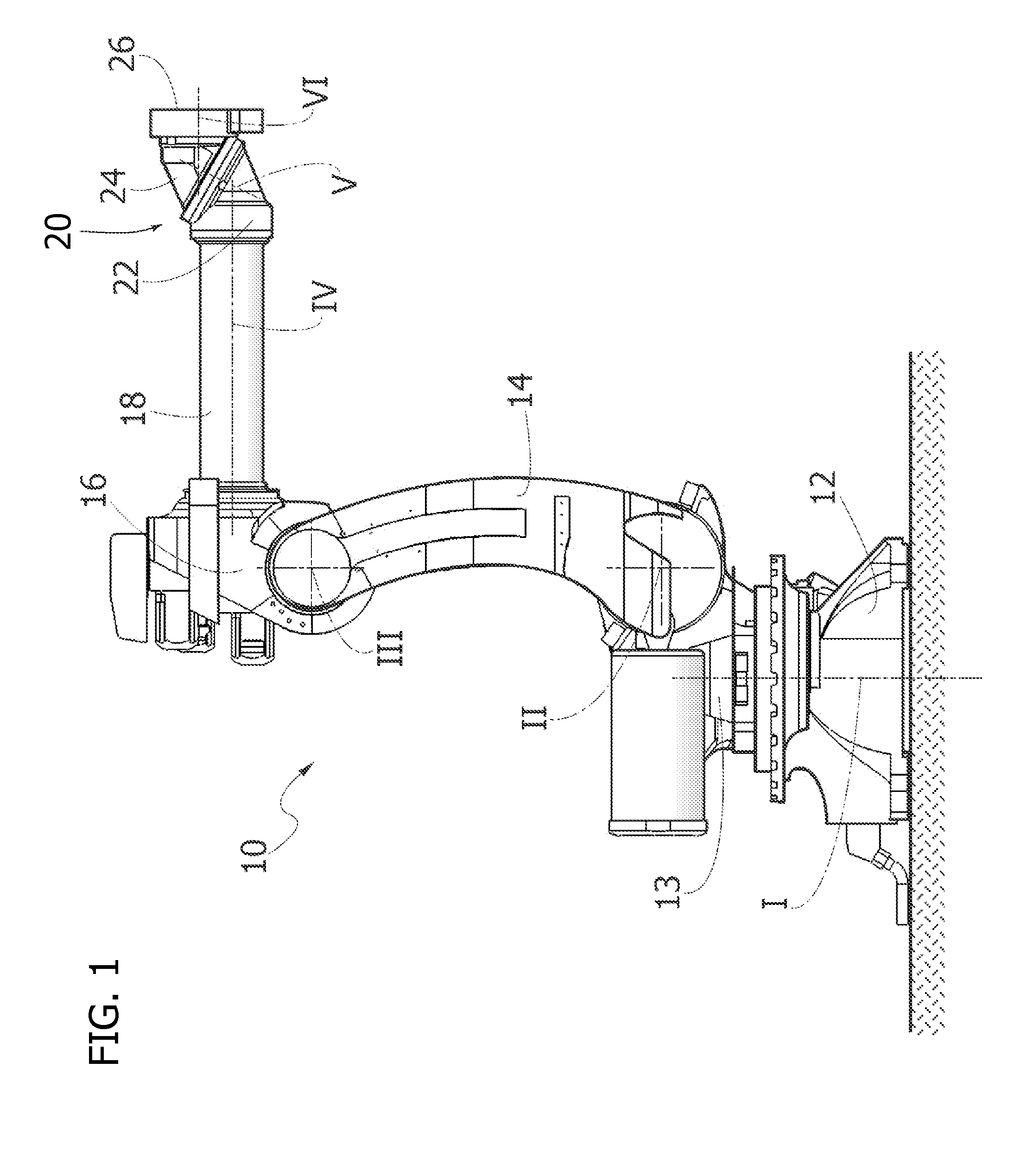
[0040]FIG. 3 of the accompanying drawings shows the robot according to the invention. In this figure, the parts common to those of FIG. 1 are designated by the same reference number.

[0041]FIG. 3 shows an embodiment in which the robot has an integrated tool consisting of an electric spot welding head, of the type in which one of the two electrode-holding arms is fixed, while the other arm is oscillatingly mounted. In place of such a welding head with oscillating arm, it is possible, however, to provide a welding head of the illustrated type of FIGS. 13 and 17, in which one of the two electrode-holding arms is fixed and the other arm is linearly slidable or other typology of tool.

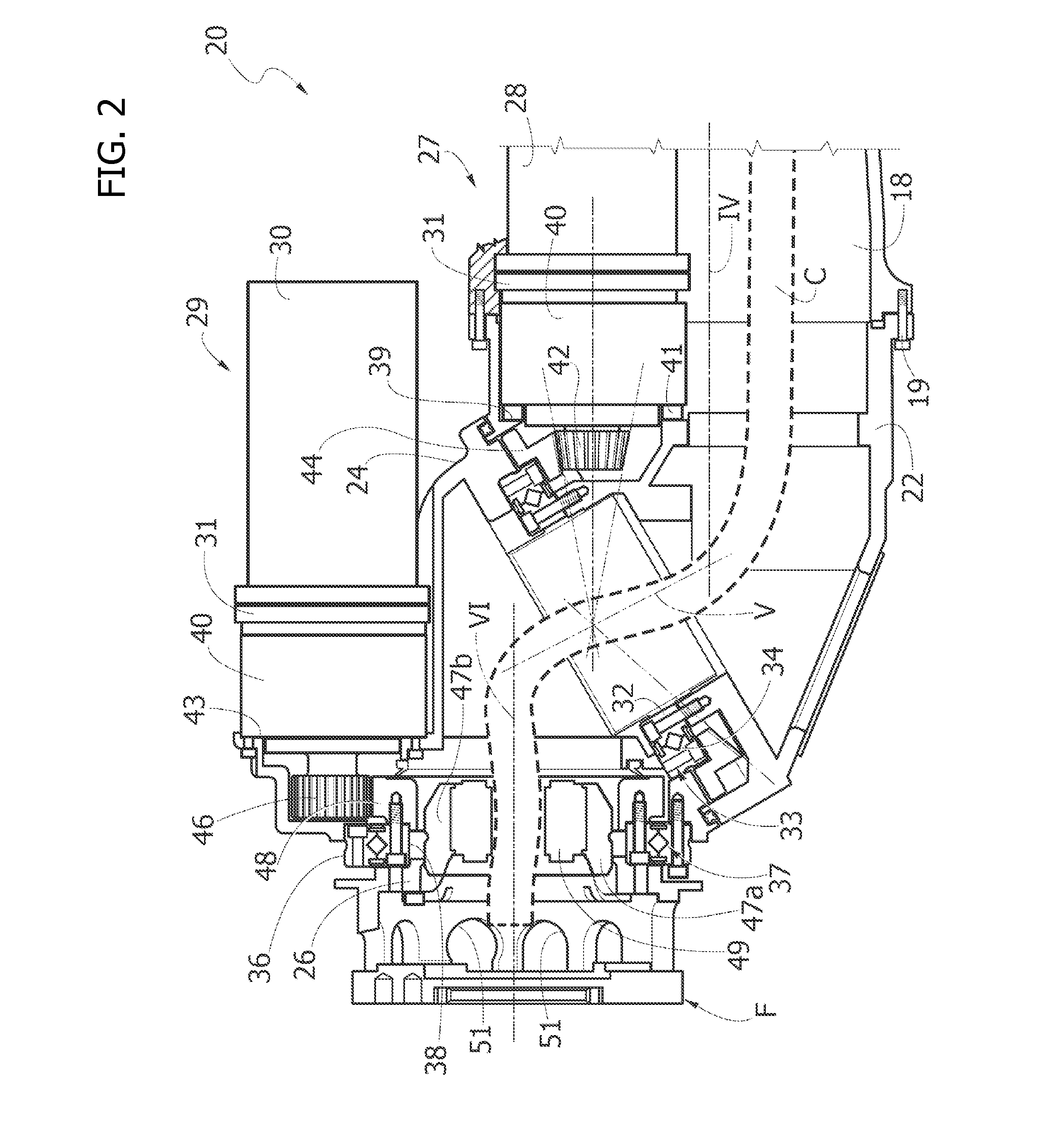
[0042]FIG. 17 of the accompanying drawings, which shows a schematic section of the robot, is particularly useful for illustrating a fundamental feature of the present invention. In this figure, the welding head is of the type with a linearly movable arm, but it is evident that what is stated here applies to b...

second embodiment

[0049]FIG. 4 shows the invention in which the robot 10 has a structure essentially identical to that of the robot of FIG. 3 but is mounted in the inverted position, with the base structure 12 fixed to a “ceiling”13 (an overhead frame) of an industrial plant.

[0050]FIG. 5 shows a perspective view on an enlarged scale of the welding head 100, in which it is clearly visible that the casing 105 is constituted by two half shells 105a, 105b coupled together and locked by the locking tie rod 106. FIG. 5 also shows the rear wall 107 of a connecting bracket 108, best seen in FIG. 18, serving to connect the flange F of the robot wrist to the supporting structure of the welding head. As shown in FIG. 18, the connecting bracket 108 includes the rear wall 107 and two wings 109 which are parallel and spaced, projecting orthogonally from the rear wall 107.

[0051]With reference to FIGS. 6, 7, the welding head 100 comprises a supporting structure 110, including two steel plates 111 which are parallel ...


PUM

PropertyMeasurementUnit
Lengthaaaaaaaaaa
Electric potential / voltageaaaaaaaaaa

Abstract

An industrial robot including a robot chain of elements, a robot wrist bearing a tool (100) and a continuous internal passage through which one or more cables and/or pipes for the power supply and/or the fluid supply to the tool. The cables and pipes continue without interruption through the passage and through a flange of the robot up to respective connections of said tool, whereby the cables and pipes are arranged completely inside the robot and inside the tool, without the need to provide separate cables and pipes of the tool connected to the cables and the pipes of the robot at the flange of the robot.

Description

FIELD OF INVENTION[0001]The present invention relates to the field of multi-axis industrial robots, of the type comprising a base structure, an articulated robot wrist and a chain of mutually articulated robot elements which connect said base structure to said robot wrist, wherein said robot wrist also ends with a flange, to which a tool is rigidly connected that requires a power supply and / or a fluid supply, and wherein through said chain of mutually articulated robot elements, and through said robot wrist, a continuous internal passage is defined in which one or more cables and / or pipes for said power supply and / or said fluid supply to the tool are received.Background[0002]A robot of the type specified above is, for example, described and illustrated in document U.S. Pat. No. 8,006,586 B2 owned by the same Applicant.[0003]In robots of the type specified above, the harnessing of cables and pipes for the power supply and the fluid supply to the tool carried by the robot poses severa...

Claims


Application Information

Patent Timeline
IPC IPC(8): B25J19/00B23K11/11B23K11/31B25J15/00
CPCB25J19/0029B25J15/0019Y10S901/42B23K11/314Y10S901/29B23K11/115B23K11/36Y10T74/20311B25J19/00
Inventor FERRERO, FULVIOMAULETTI, ENRICO
Owner COMAU SPA
Why Eureka
Try Eureka