Color imaging element and imaging device

a color imaging element and imaging device technology, applied in the direction of radioation controlled devices, television system scanning details, television systems, etc., can solve the problems of poor pixel reproduction precision in the limit resolution area (especially in the oblique direction), complex demosaicing process, and deterioration of high-frequency reproducibility, etc., to simplify processing, perform signal processing, and simplify processing

Active Publication Date: 2015-04-23
FUJIFILM CORP
View PDF3 Cites 12 Cited by
  • Summary
  • Abstract
  • Description
  • Claims
  • Application Information

AI Technical Summary

Benefits of technology

[0035]Since the color imaging element and imaging device of the present invention includes a color filter array in which a basic array pattern is repeatedly disposed in the first direction and the second direction, it is possible to perform processing according to the repeating pattern when performing demosaicing process in a subsequent stage, and it is possible to simplify processing in the subsequent stage as compared with a random array in the related art. Since it is possible to perform signal processing such as demosaicing more easily as the size of the basic array pattern (repeating pattern) becomes small, in the present invention, it is possible to further simplify processing in the subsequent stage as compared with a case where a color filter array including the random array in the related art and a large-size repeating array pattern is used.
[0036]Moreover, the first filter is disposed in the line of each direction of the first to fourth directions of a color filter array and the ratio of the pixel number of the first color corresponding to the first filter is made larger than the ratios of the pixel numbers of the second colors that are two or more colors excluding the first color and correspond to the second filter, it is possible to improve the reproduction precision of demosaicing process in a high-frequency area and suppress aliasing.
[0037]Moreover, since the second filter of each color of the second colors is disposed in two filter lines of each filter line of the first direction of the basic array pattern and the second filter of at least one color of each color of the second colors is disposed in each filter line of the second direction, it is possible to reduce the occurrence of color moire (false color) and prevent the degradation of resolution.

Problems solved by technology

In the color imaging element described in PTL 1, since the color filter array is random, when demosaicing process is performed in a subsequent stage, optimization has to be performed every random pattern, and there is a problem that the demosaicing process becomes complex.
Moreover, in the color imaging element described in PTL 2, since the G pixels (brightness pixels) are disposed in a checkered pattern, there is a problem that the pixel reproduction precision in a limit resolution area (especially in an oblique direction) is not good.
In the color imaging element described in PTL 3, since the ratios of RGB pixel numbers are equal, there is a problem that the high-frequency reproducibility deteriorates as compared with the Bayer array.

Method used


Image

  • Color imaging element and imaging device
  • Color imaging element and imaging device
  • Color imaging element and imaging device

Examples


first embodiment

[Color Filter Array of the First Embodiment]

[0071]The color filter array 22 has following features (1), (2), (3), (4), (5) and (6).

[Feature (1)]

[0072]As illustrated in FIGS. 3 and 4, the color filter array 22 includes a basic array pattern P1 that is a square array pattern corresponding to 3×3 pixels, and this basic array pattern P1 is repeatedly disposed on the horizontal direction (H) and the vertical direction (V). Therefore, the R filter 23R, the G filter 23G and the B filter 23B of the respective colors are arrayed in a predetermined period in the color filter array 22. Therefore, when performing demosaicing process or the like on R, G and B signals read out from the color imaging element 12, it is possible to perform processing according to a repeating pattern. As a result, it is possible to simplify processing in the subsequent stage as compared with a random array in the related art.

[0073]Moreover, in a case where thinning processing is performed in units of the basic array ...

second embodiment

[Color Imaging Element of Second Embodiment]

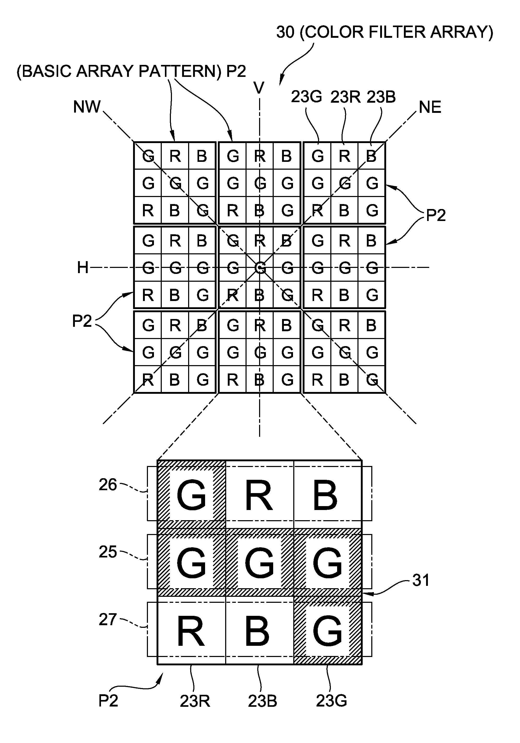
[0087]Next, a color imaging element of the second embodiment of the present invention is described using FIG. 8. Here, the color imaging element of the second embodiment has the basically the same configuration as the above-mentioned first embodiment except for that it includes a color filter array 30 having an array pattern different from the color filter array 22 of the above-mentioned first embodiment. Therefore, regarding what has the same function or configuration as that of the above-mentioned first embodiment, the same reference numeral is assigned and explanation thereof is omitted.

[Color Filter Array of Second Embodiment]

[0088]The color filter array 30 includes a basic array pattern P2 formed by arraying RGB filters 23R, 23G and 23B in an array pattern corresponding to 3×3 pixels, and this basic array pattern P2 is repeatedly disposed in the horizontal direction (H) and the vertical direction (V). Therefore, the color filter array...

fourth embodiment

[Color Imaging Element of Fourth Embodiment]

[0109]Next, the color imaging element of the fourth embodiment of the present invention is described using FIG. 12. Here, the color imaging element of the fourth embodiment has basically the same configuration as that of above-mentioned first embodiment except for that it includes two kinds of G pixels. Therefore, regarding what has the same function or configuration as that of the above-mentioned first embodiment, the same reference numeral is assigned and explanation thereof is omitted.

[Color Filter Array of Fourth Embodiment]

[0110]The color imaging element of the fourth embodiment includes a color filter array 40 different from that of the first embodiment. The color filter array 40 includes a basic array pattern P4 in which the R filter 23R, a first G filter 23G1 and a second G filter 23G2 (first filter) and the B filter 23B are arrayed in an array pattern corresponding to 3×3 pixels, and this basic array pattern P4 is repeatedly dispo...


PUM


Abstract

A color filter array is configured with a 3×3 basic array pattern repeatedly disposed in a horizontal and a vertical direction. The basic array pattern is configured with a G filter array formed by disposing a G filter in the horizontal direction, and first and the second RGB filter arrays formed by disposing RGB filters in the horizontal direction. The ratio of the pixel number of the G color is made larger than the ratio of the pixel number of each color of RB. The G filter is disposed in each filter line in the horizontal, vertical and oblique directions of the color filter array. The RB filters are each disposed in one filter line in the vertical direction of the basic array pattern, and any of the RB filters is disposed in other filter lines.

Description

CROSS-REFERENCE TO RELATED APPLICATIONS[0001]This application is a Continuation of PCT International Application No. PCT / JP2013 / 068233 filed on Jul. 3, 2013, which claims priority under 35 U.S.C §119(a) to Japanese Patent Application No. 2012-152680 filed on Jul. 6, 2012. Each of the above applications is hereby expressly incorporated by reference, in their entirety, into the present application.BACKGROUND OF THE INVENTION[0002]1 . Field of the Invention[0003]The present invention relates to a single-plate color imaging element in which a color filter is arranged on a pixel, and an imaging device including such a color imaging element.[0004]2. Description of the Related Art[0005]In the single-plate color imaging element, since the monochromatic color filter is set on each pixel, each pixel has only monochrome color information. Therefore, since the output image of the single-plate color imaging element is a RAW image (mosaic image), a multi-channel image is acquired by processing (d...

Claims


Application Information

Patent Timeline
Patent Type & Authority Applications(United States)
IPC IPC(8): H01L27/146H04N9/04
CPCH04N9/045H01L27/14621H04N23/843H04N25/134
Inventor TANAKA, SEIJIHAYASHI, KENKICHI
Owner FUJIFILM CORP
Why Eureka
Try Eureka