
Rotor with a backplane bus having electrical connection elements to make electrical contact with electrical components in a medical apparatus, as well as rotating unit and medical apparatus with such a rotor

a backplane and electrical connection technology, applied in the field of rotors of computed tomography (ct) apparatus, can solve the problems of increasing total costs, unstable and long-lasting electrical connections, and increasing power transfer and data exchange, so as to simplify the electrical contact of electrical components, simple design, installation and deinstallation or

Inactive Publication Date: 2015-04-23
SIEMENS HEALTHCARE GMBH
View PDF5 Cites 2 Cited by
  • Summary
  • Abstract
  • Description
  • Claims
  • Application Information

AI Technical Summary

Benefits of technology

The invention is a medical imaging apparatus, specifically a computed tomography apparatus, that simplifies the electrical contacting of its components. The rotor of the apparatus has a mechanical support frame and a backplane bus with electrical connection elements for easy connection with the electrical components. The electrical connection elements are integrated into the backplane bus, allowing for easy installation, deinstallation, and exchange of the components. The rotor also has a continuous recess for attaching different electrical components, which can be mechanically attached and electrically connected to the backplane bus. The electrical connection between the components and the backplane bus can also be achieved through a mechanical shorting of the components, further simplifying the installation process. Overall, the invention simplifies the installation, deinstallation, and exchange of electrical components in the medical imaging apparatus.

Problems solved by technology

An immense power transfer and an intensive data exchange occur between the stationary part and the rotating part of the gantry of a CT apparatus.
However, in rotating systems this type of connection is only conditionally advantageous due to the centrifugal forces acting on the components and the partial mobility of the cables.
At high velocities or given velocity changes, the stability and the longevity of such electrical connections are problematical, particularly given the transmission of large amounts of electrical power.
Moreover, the cable connections consume a large amount of material (in particular copper), so the total costs are increased.
Given each additional component to be attached to the rotating part, the number of cables, the material costs and the weight of the apparatus thus increase.
The integration of new components on the rotating part is also complicated due to the cables and cable anchoring devices that are already present.
Lastly, the cable connections must be individually mounted and attached, which is complicated.
In the event of service, for example for the exchange of a component, first these must be individually demounted and attached again, which increases the work time.

Method used


Image

  • Rotor with a backplane bus having electrical connection elements to make electrical contact with electrical components in a medical apparatus, as well as rotating unit and medical apparatus with such a rotor
  • Rotor with a backplane bus having electrical connection elements to make electrical contact with electrical components in a medical apparatus, as well as rotating unit and medical apparatus with such a rotor
  • Rotor with a backplane bus having electrical connection elements to make electrical contact with electrical components in a medical apparatus, as well as rotating unit and medical apparatus with such a rotor

Examples


Embodiment Construction

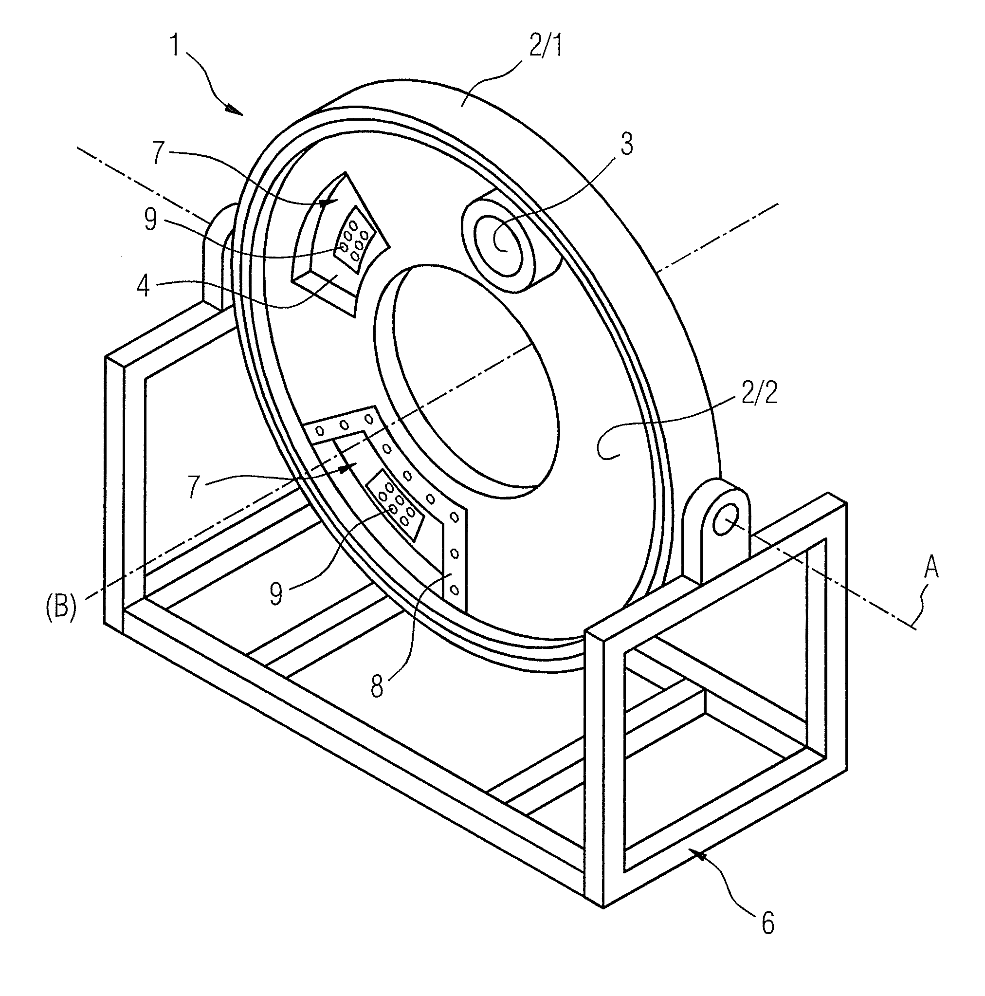
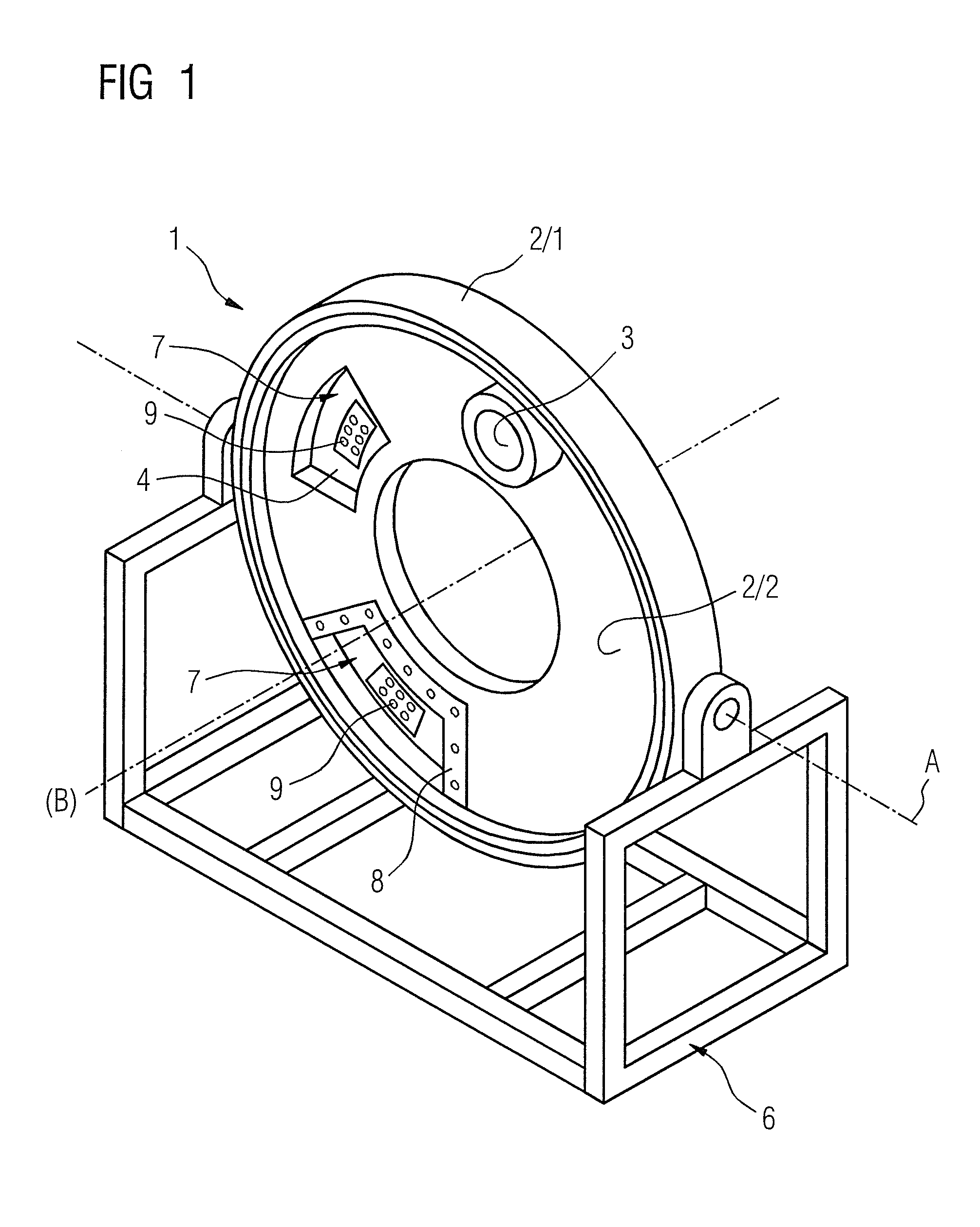
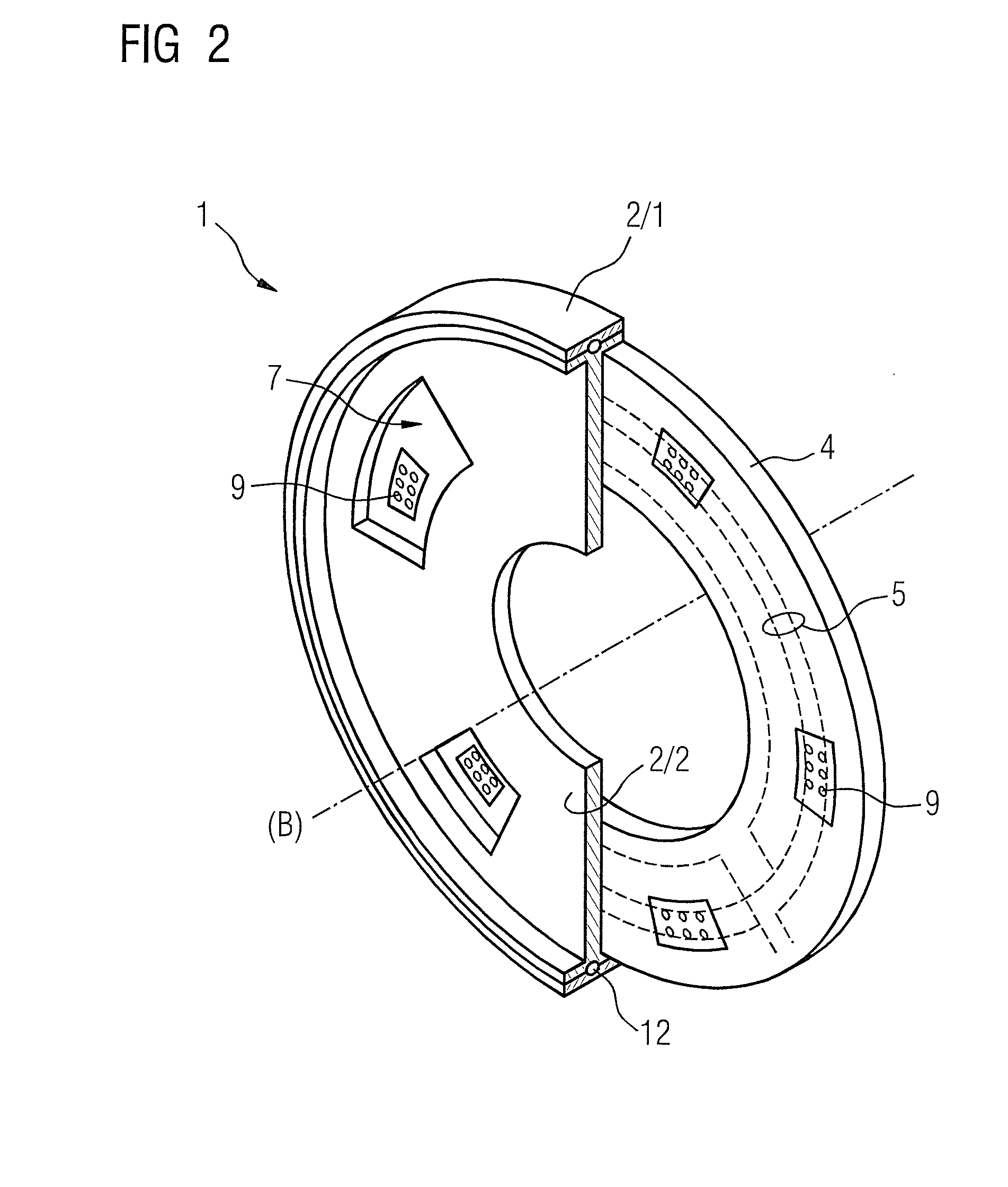
[0029]FIG. 1 is a schematic depiction of a tiltable rotor 1 of a computed tomography apparatus with a stationary mechanical frame 2 / 1, the electrical component 3 over a bearing with a rotatable mechanical frame 2 / 2 as mechanical mount, and a backplane bus 4 attached laterally to the rotatable mechanical frame 2 / 2. The rotor 1 is supported or mounted so as to be tiltable on an axis A, relative to a stationary part 6. The rotatable mechanical frame 2 / 2 has various continuous recesses 7, which are designed for the accommodation of different electrical components 3. The rotatable mechanical frame 2 / 2 also has attachment surfaces 8 which, for example, are formed around the continuous recesses 7 for accommodation of the electrical component 3. The backplane bus 4 has electrical connection elements 5 for electrical contacting of the electrical component 3. In particular, the backplane bus 4 has electrical feed lines which are integrated into said backplane bus 4, as well as connectors 9—fa...


PUM


Abstract

A rotor of a computed tomography apparatus has a rotatable mechanical support frame for mechanical retention of electrical components and electrical connection elements for electrical connection with electrical components of the computed tomography apparatus, with the electrical connection elements arranged in at least one backplane bus. A rotating unit and a computed tomography apparatus embody such a rotor.

Description

BACKGROUND OF THE INVENTION[0001]1. Field of the Invention[0002]The invention concerns a rotor of a computed tomography (CT) apparatus with a rotatable mechanical support frame for mechanical retention of electrical components and electrical connection elements for electrical connection with electrical components of the computed tomography apparatus, wherein the electrical connection elements are arranged in at least one backplane bus. Furthermore, the invention concerns a rotating unit and a computed tomography apparatus with such a rotor.[0003]2. Description of the Prior Art[0004]Computed tomography apparatuses are used often for medical imaging,—a primary field of apparatus of the present invention. A computed tomography apparatus essentially has a stationary part and a rotating or rotatable part, and the rotatable part has an acquisition system that includes at least one radiation source and one detector attached to a frame that is mounted such that it can rotate. Such a rotatab...

Claims


Application Information

Patent Timeline
Patent Type & Authority Applications(United States)
IPC IPC(8): A61B6/03H01R39/10A61B6/00H05K1/00
CPCA61B6/035A61B6/4476H01R39/10H05K1/00A61B6/4447A61B6/56H01R2201/12
Inventor DISTLER, FRIEDRICHHAIDER, SULTANMUELLER, HANS-JUERGEN
Owner SIEMENS HEALTHCARE GMBH
Learn More