Magnetic coupling with low moment articulated plug

a technology of articulated plugs and magnets, applied in the field of optical communication, can solve the problems of affecting the accuracy of the mated plug, the inability to accurately match, and the damage to the electronic device, so as to reduce the moment arm

Active Publication Date: 2015-04-23
CORNING OPTICAL COMM LLC
View PDF13 Cites 22 Cited by
  • Summary
  • Abstract
  • Description
  • Claims
  • Application Information

AI Technical Summary

Benefits of technology

[0008]In embodiments, a plug for connecting to an electronic device is disclosed. The plug may comprise a housing having a first surface, a first aperture in the first surface, and a second surface; a magnetic element positioned in the first aperture and having a second aperture; at least one contact within the first aperture and the second aperture; a cord connected to the second surface of the housing; and a mechanism configured to reduce a moment arm on the housing when a force is applied to the cord.

Problems solved by technology

However, using this type of connection, damage may occur to the male connector, the female connector, and / or the electronic device in a number of ways especially in consumer applications.
For example, force applied to the cable can cause the male connector and the female connector to be demated at an angle that bends the male connector and / or damages the female connector such that accurate mating is no longer possible.
In another example, if force is applied to the cable and the male connector and female connector do not demate, the electronic device may be pulled so that it falls from a surface on which it was sitting, thereby causing damage to the electronic device.
However, a precise connection between optical fibers in, for example, a cable assembly and an electronic device must be provided to ensure uninterrupted transfer of data.

Method used


Image

  • Magnetic coupling with low moment articulated plug
  • Magnetic coupling with low moment articulated plug
  • Magnetic coupling with low moment articulated plug

Examples


Embodiment Construction

[0030]Reference will now be made in detail to the embodiments of the disclosure, examples of which are illustrated in the accompanying drawings. Whenever possible, like reference numbers will be used to refer to like components or parts.

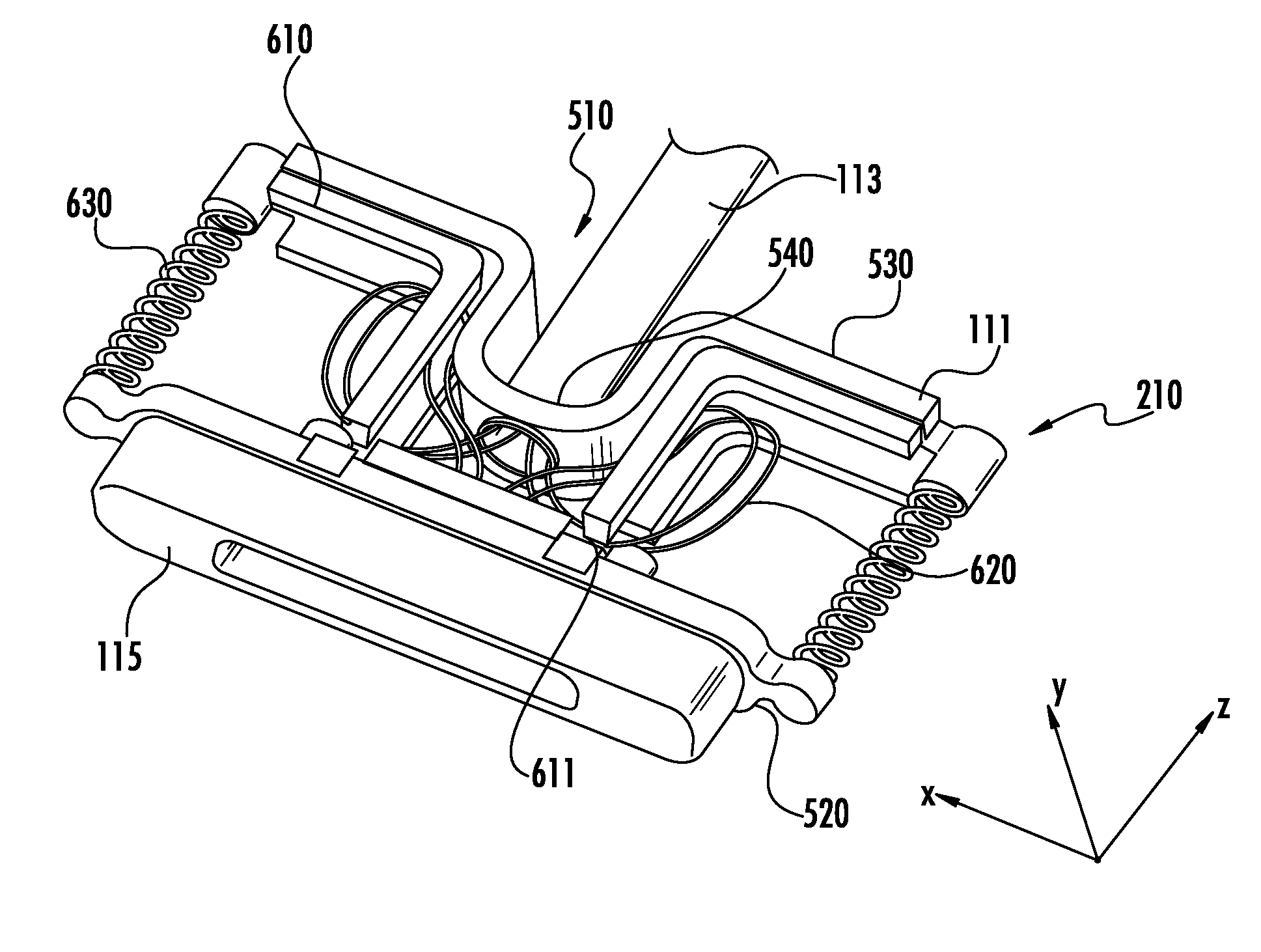
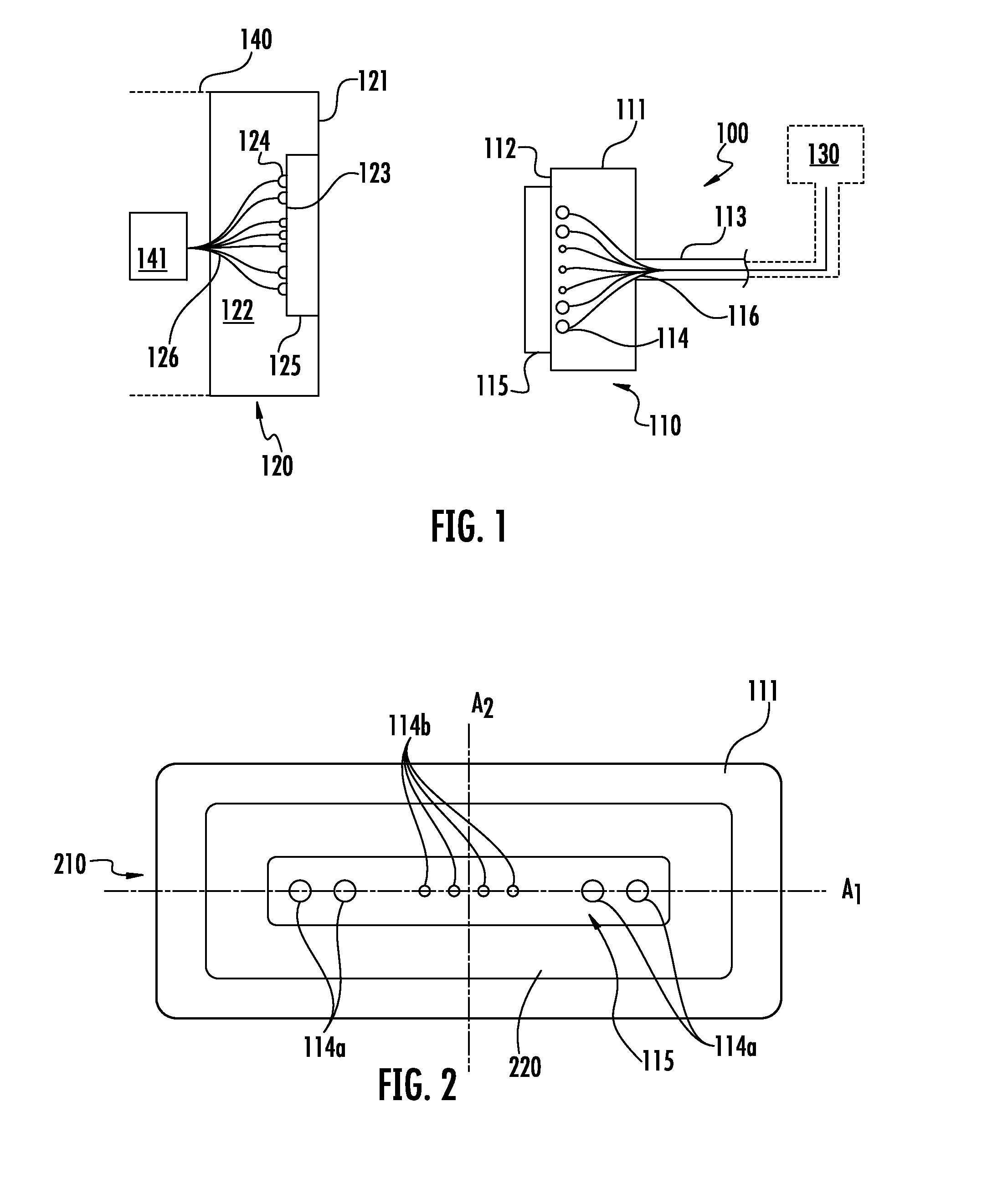
[0031]Referring to FIG. 1, an embodiment of a connector 100 according to the present disclosure is illustrated in a cross-sectional view. The magnetic connector 100 includes a first connector or plug 110 (hereinafter referred to as the “plug”) and a second connector or receptacle 120 (hereinafter referred to as the “receptacle”). In embodiments, the plug 110 may be connected to an electronic device or electrical relation 130, and the receptacle 120 may be embedded within a second electronic device 140. In embodiments, the first electronic device 130 may comprise a transformer and / or a data transmitter, and the second device 140 may be a laptop computer, a tablet computer, a cellular phone, display, or a handheld electronic device having a housing 121...


PUM


Abstract

A plug for connecting to an electronic device includes a housing having an aperture, a magnetic element positioned in the aperture and having a second aperture, at least one contact within the aperture and the second aperture, a cord connected to the housing, and a mechanism configured to reduce a moment arm on the housing when a force is applied to the cord. The plug may be used as part of a connection that further includes a receptacle having a magnetic element with a recess, wherein the recess comprises an aperture, and at least one contact extending through the third aperture and into the recess.

Description

BACKGROUND[0001]1. Field of the Disclosure[0002]The present disclosure generally relates to optical communication and, more particularly, to providing power and / or optical communication to an electronic device using a connector such as a plug having a magnetic connection that may be part of a connector system having a complimentary receptacle for the plug.[0003]2. Technical Background[0004]Conventional data and / or power connections comprise female connectors and male connectors. The male connecter generally includes a cable that transmits a data signal or power, and the female connector is generally included in an electronic device. The mating of the male and female connectors provides a stable connection between the cable and the components that allows reliable data and / or power transfer across the cable and to the electronic device. Typical male and female connectors may include a mechanical interlock such as metal shells, pins or the like for securing the connection.[0005]However...

Claims


Application Information

Patent Timeline
Patent Type & Authority Applications(United States)
IPC IPC(8): H01R13/62
CPCH01R13/6205G02B6/3817G02B6/3821G02B6/3885G02B6/3886
Inventor ISENHOUR, MICAH COLENLUTHER, JAMES PHILLIP
Owner CORNING OPTICAL COMM LLC
Why Eureka
Try Eureka