

Angular velocity sensor, electronic apparatus, and moving object
a technology of angular velocity sensor and electronic apparatus, applied in the direction of acceleration measurement using interia force, instruments, devices using electric/magnetic means, etc., can solve the problems of attenuating rotational vibration, output fluctuation, and degrading detection accuracy and the like, and achieve excellent reliability
- Summary
- Abstract
- Description
- Claims
- Application Information
AI Technical Summary
Benefits of technology
Problems solved by technology
Method used
Image

Examples
first embodiment
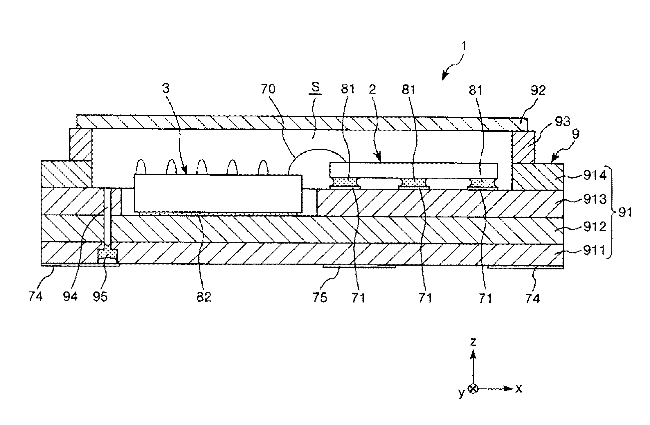
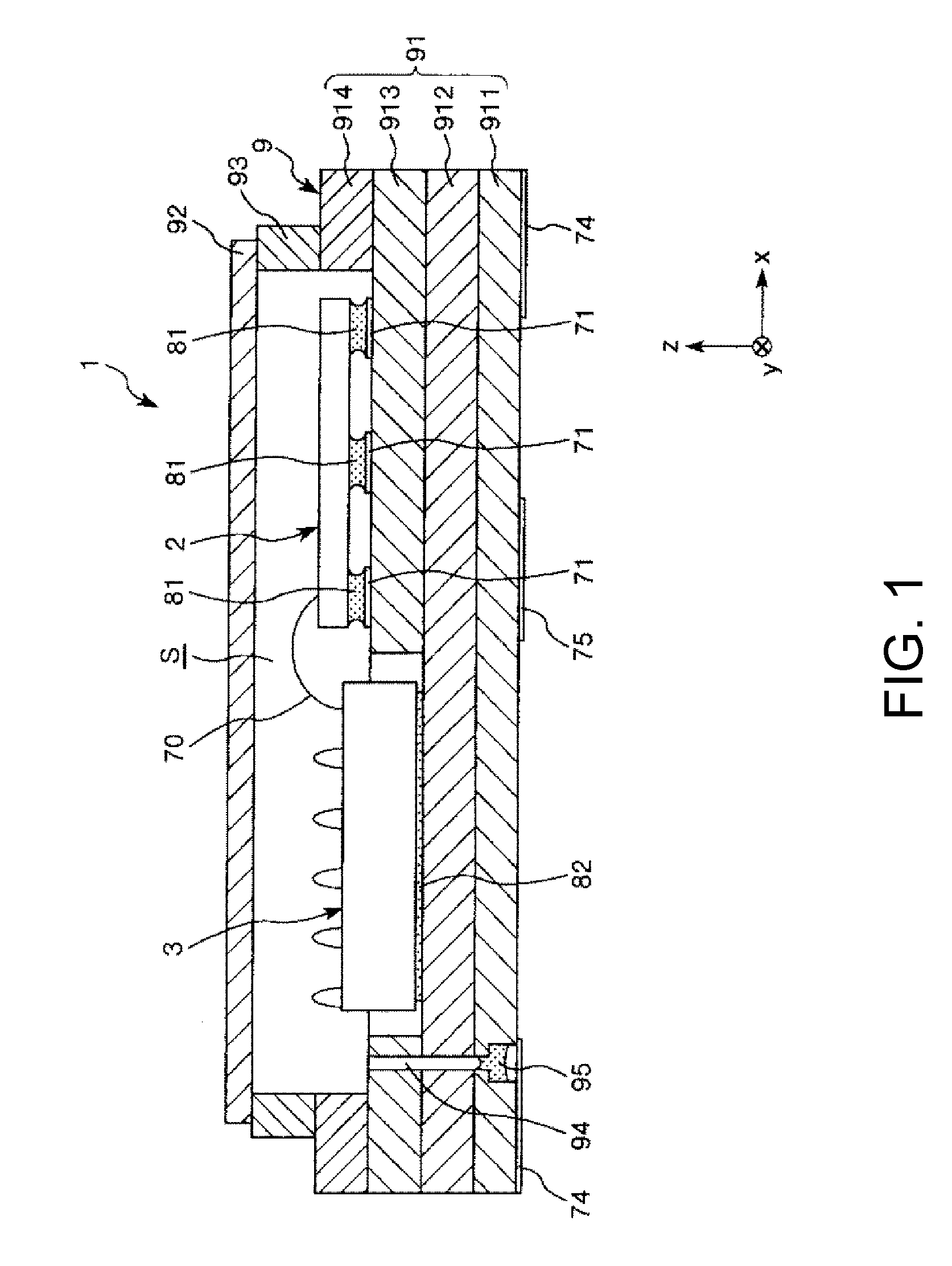
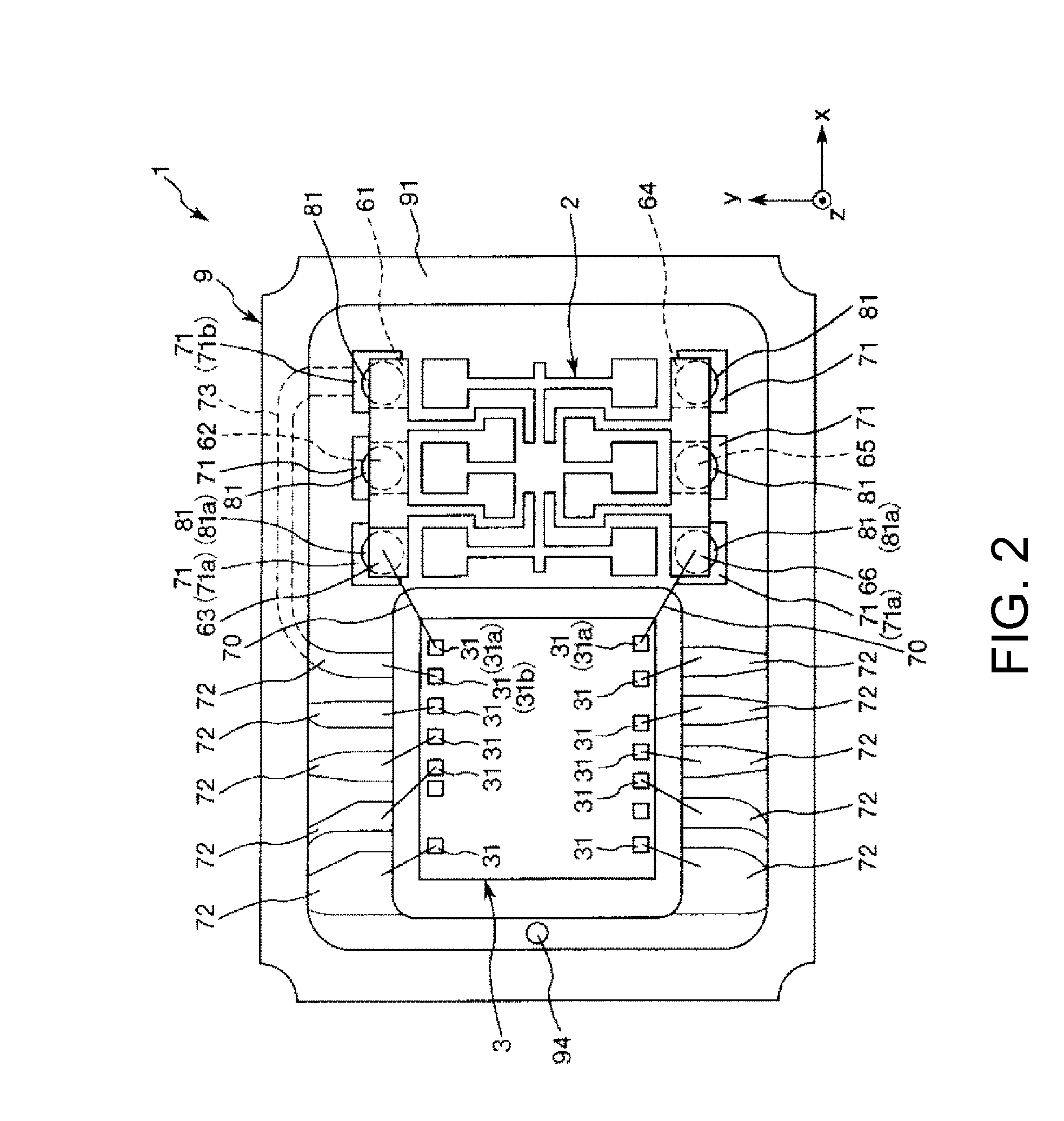
[0047]FIG. 1 is a cross-sectional view showing a schematic configuration of an angular velocity sensor according to a first embodiment of the invention. FIG. 2 is a plan view of the angular velocity sensor shown in FIG. 1. FIG. 3 is a plan view of a sensor element included in the angular velocity sensor shown in FIG. 1. FIGS. 4A and 4B are plan views illustrating the operation of the sensor element shown in FIG. 3.
[0048]Meanwhile, in FIGS. 1 to 4, an x-axis, a y-axis, and a z-axis are shown as three mutually perpendicular axes for convenience of description, and a tip end side of an arrow shown in the drawing is assumed to be “+(positive)” and a base end side is assumed to be“−(negative)”. In addition, hereinafter, a direction parallel to the x-axis is referred to as an “x-axis direction”, a direction parallel to a y-axis is referred to as a “y-axis direction”, a direction parallel to a z-axis is referred to as a “z-axis direction”, a +z side (upper side in FIG. 1) is referred to as...
second embodiment
[0127]Next, a second embodiment of the invention will be described.
[0128]FIG. 7A is a plan view showing a schematic configuration of an angular velocity sensor according to the second embodiment of the invention, and FIG. 7B is a cross-sectional view taken along line A-A in FIG. 7A. In addition, FIG. 8 is a rear view illustrating a supporting unit included in the angular velocity sensor shown in FIGS. 7A and 7B.
[0129]Hereinafter, the second embodiment will be described focusing on the differences from the above-described embodiment, and the description of similar matters will be omitted. Meanwhile, the same components as those in the first embodiment mentioned above will be denoted by the same reference numerals and signs.
[0130]An angular velocity sensor 1A of this embodiment includes a sensor element 2A, an IC chip 3, a package 9 that accommodates the sensor element 2A and the IC chip 3, and a supporting member 4 that supports the sensor element 2A with respect to the package 9.
[01...
third embodiment
[0147]Next, a third embodiment of the invention will be described.
[0148]FIG. 9 is a plan view showing a schematic configuration of an angular velocity sensor according to the third embodiment of the invention. FIG. 10 is a plan view illustrating the operation of a sensor element included in the angular velocity sensor shown in FIG. 9. In addition, FIG. 11A is a diagram showing a simplified model related to the rotational vibration of the angular velocity sensor shown in FIG. 12, and FIG. 11B is a diagram showing a primary rotational vibration mode (mode 1) around a detection axis.
[0149]Hereinafter, the third embodiment will be described focusing on the differences from the above-described embodiments, and the description of similar matters will be omitted. Meanwhile, the same components as those in the first embodiment mentioned above will be denoted by the same reference numerals and signs.
[0150]An angular velocity sensor 1B of this embodiment includes a sensor element 2B, an IC ch...
PUM
 Abstract
Description
Claims
Application Information