Durability test device of membrane electrode assembly and durability test method thereof
- Summary
- Abstract
- Description
- Claims
- Application Information
AI Technical Summary
Benefits of technology
Problems solved by technology
Method used
Image

Examples
first embodiment
A. First Embodiment
[0025](A1) Durability Test Device:
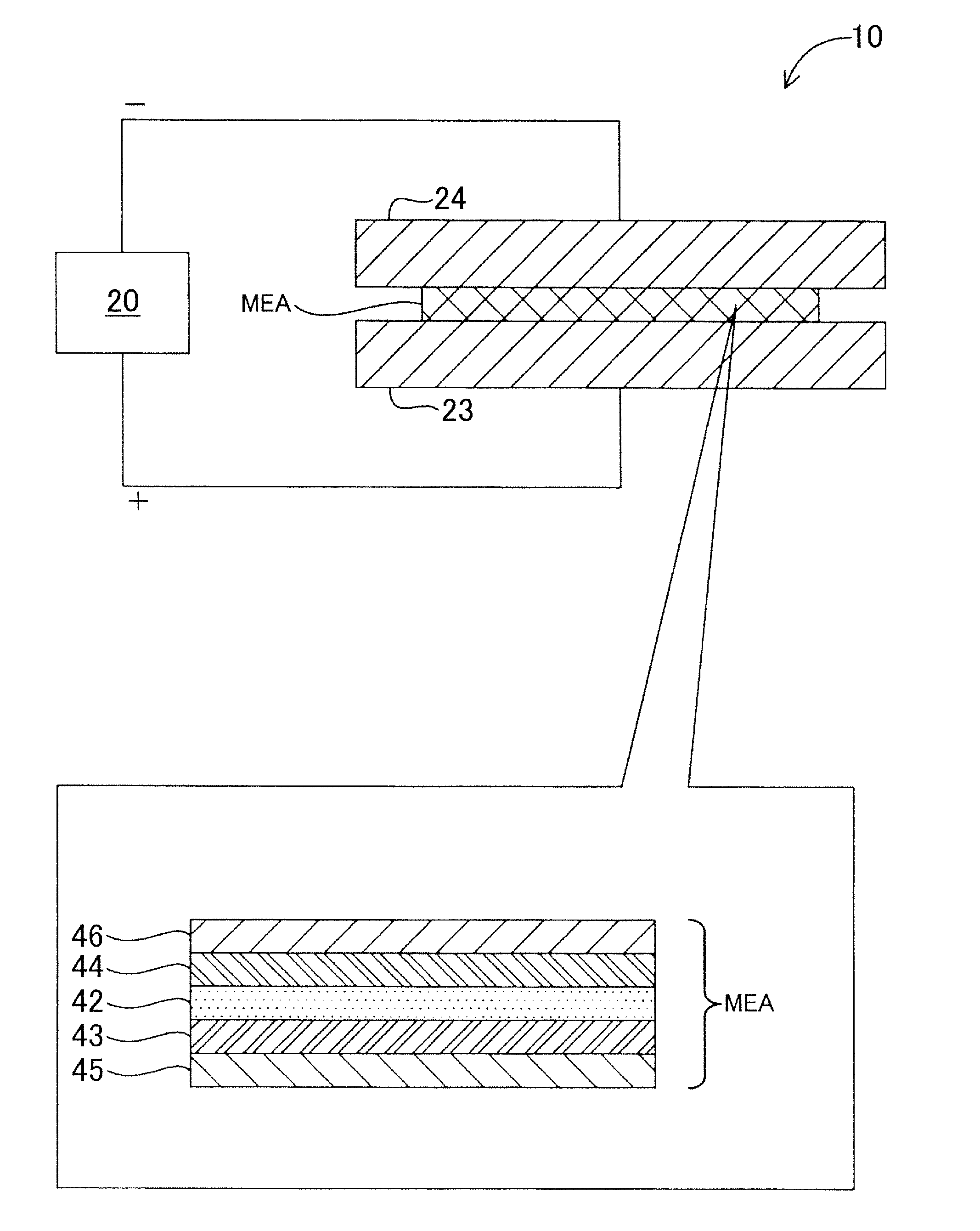
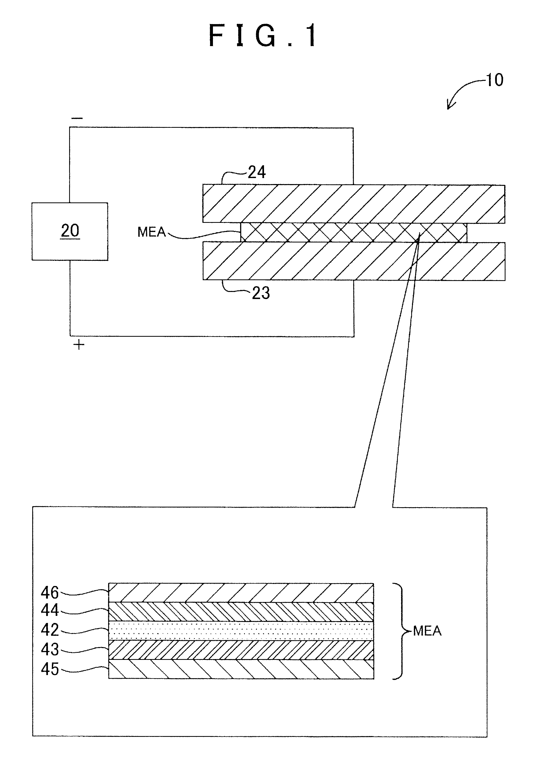
[0026]FIG. 1 is a schematic view illustrating a configuration of a durability test device 10 as a first embodiment of the present invention. The durability test device 10 is a device for examining durability of a membrane electrode assembly MEA used for a fuel cell by applying a voltage to the membrane electrode assembly MEA while sweeping the voltage in a predetermined voltage region.
[0027]The durability test device 10 includes a measurement control section 20, a positive electrode 23, and a negative electrode 24. The positive electrode 23 and the negative electrode 24 are electrically connected to the measurement control section 20. The measurement control section 20 applies a voltage between the positive electrode 23 and the negative electrode 24, and measures a current flowing between the electrodes. The measurement control section 20 can sweep a voltage to be applied between the electrodes in a predetermined voltage region. F...
modified example 1
(B1) Modified Example 1
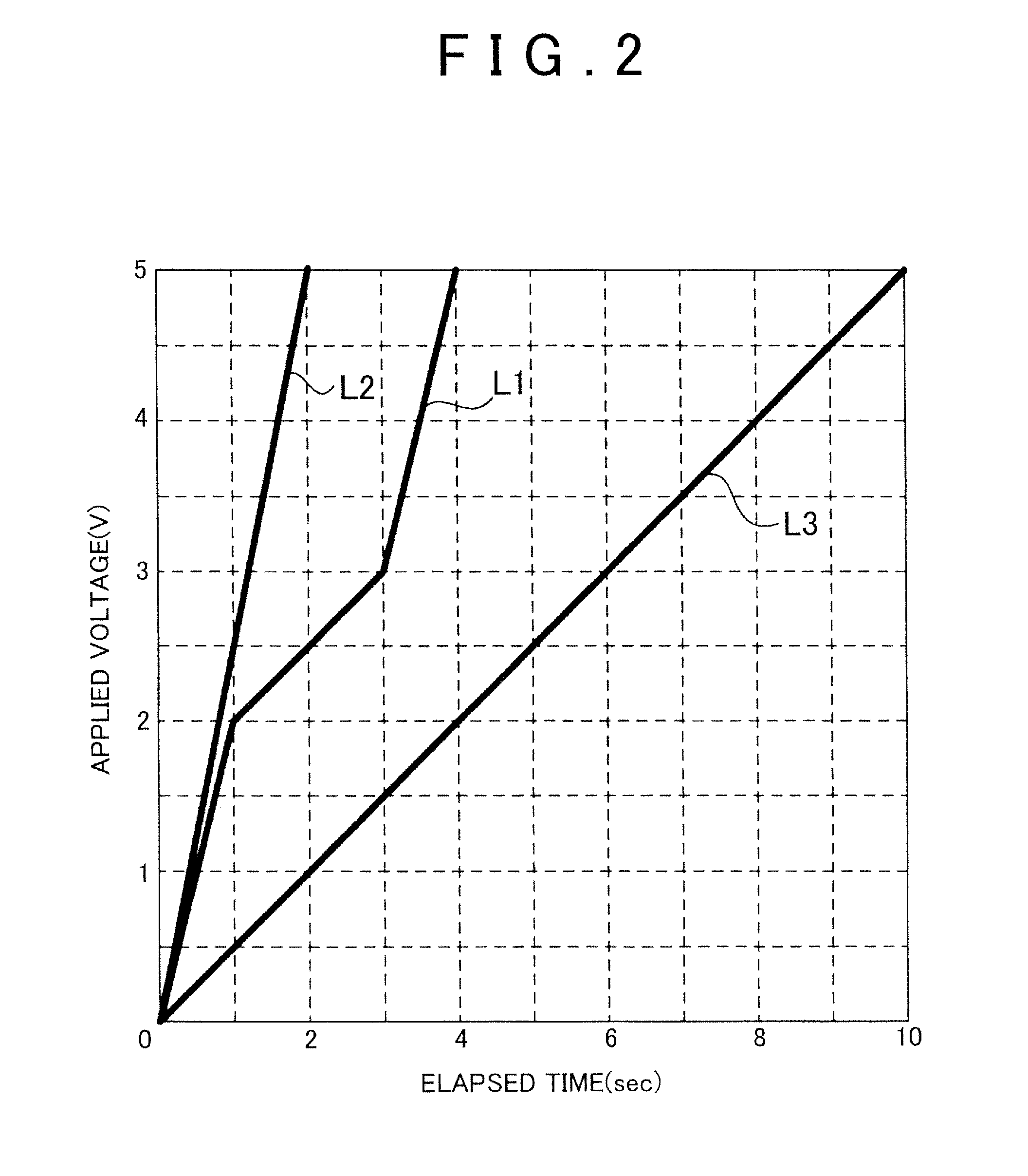
[0046]In the first sweep method as the above embodiment, the sweep rate shown by the graph L1 in FIG. 2 is used as the sweep rate, but various patterns of the sweep rate can be employed provided that the sweep rate is lower in the voltage region where the carbon oxidation peak is measured than the other voltage regions. For example, the sweep rate in a voltage region of 0 V to 1.5 V may be 2.5 V / sec, the sweep rate in a voltage region of 1.5 V to 4.0 V may be 0.3 V / sec, and the sweep rate in a voltage region of 4.0 V to 5.0 V may be 2.0 V / sec. Even in this case, it is possible to obtain the same effect as in the above embodiment.
example 2
(B2) Modified Example 2
[0047]In the above embodiment, the region (0 V to 5 V) of the voltage to be swept is divided into three regions (0 V to 2 V, 2 V to 3 V, 3 V to 5 V), but may be divided into two regions of 0 V to 3 V and of 3 V to 5 V such that the sweep rate in the voltage region of 0 V to 3 V is set lower than the sweep rate in the voltage region of 3 V to 5 V. Moreover, for example, the voltage region may be divided into two regions of 0 V to 2 V and of 2 V to 5 V such that the sweep rate in the voltage region of 2 V to 5 V is set lower than the sweep rate in the voltage region of 0 V to 2 V. Thus, it is possible to employ various forms as a division form of the region of the voltage to be swept as long as the sweep rate in the voltage region where the carbon oxidation peak is measured is set lower than that in the other voltage region.
PUM
 Abstract
Description
Claims
Application Information
 - Generate Ideas
- Intellectual Property
- Life Sciences
- Materials
- Tech Scout
- Unparalleled Data Quality
- Higher Quality Content
- 60% Fewer Hallucinations
Browse by: Latest US Patents, China's latest patents, Technical Efficacy Thesaurus, Application Domain, Technology Topic, Popular Technical Reports.
© 2025 PatSnap. All rights reserved.Legal|Privacy policy|Modern Slavery Act Transparency Statement|Sitemap|About US| Contact US: help@patsnap.com