Pressure Generator of a Hydraulic Vehicle Brake System and Operating Method for This

a technology of hydraulic brake system and pressure generator, which is applied in the direction of braking system, coupling, mechanical apparatus, etc., to achieve the effect of safe and reliable operation

Active Publication Date: 2011-05-12
LUCAS AUTOMOTIVE GMBH
View PDF4 Cites 0 Cited by
  • Summary
  • Abstract
  • Description
  • Claims
  • Application Information

AI Technical Summary

Benefits of technology

[0012]It is therefore a feature of the present invention to provide a pressure generator which can ensure safe and reliable functioning even in the above-described braking situations without its performance in normal operation (i.e. when such peak values for a prevailing brake pressure do not occur) being reduced.

Problems solved by technology

In such a case, the actuator drives the pump pistons only to the extent that the associated pressure chambers are supplied with brake fluid (restricted delivery capacity).

Method used


Image

  • Pressure Generator of a Hydraulic Vehicle Brake System and Operating Method for This
  • Pressure Generator of a Hydraulic Vehicle Brake System and Operating Method for This
  • Pressure Generator of a Hydraulic Vehicle Brake System and Operating Method for This

Examples


Embodiment Construction

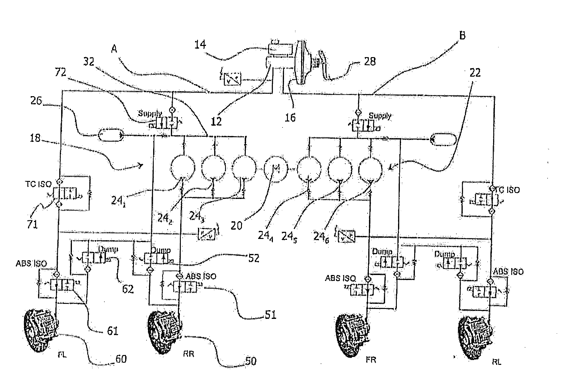
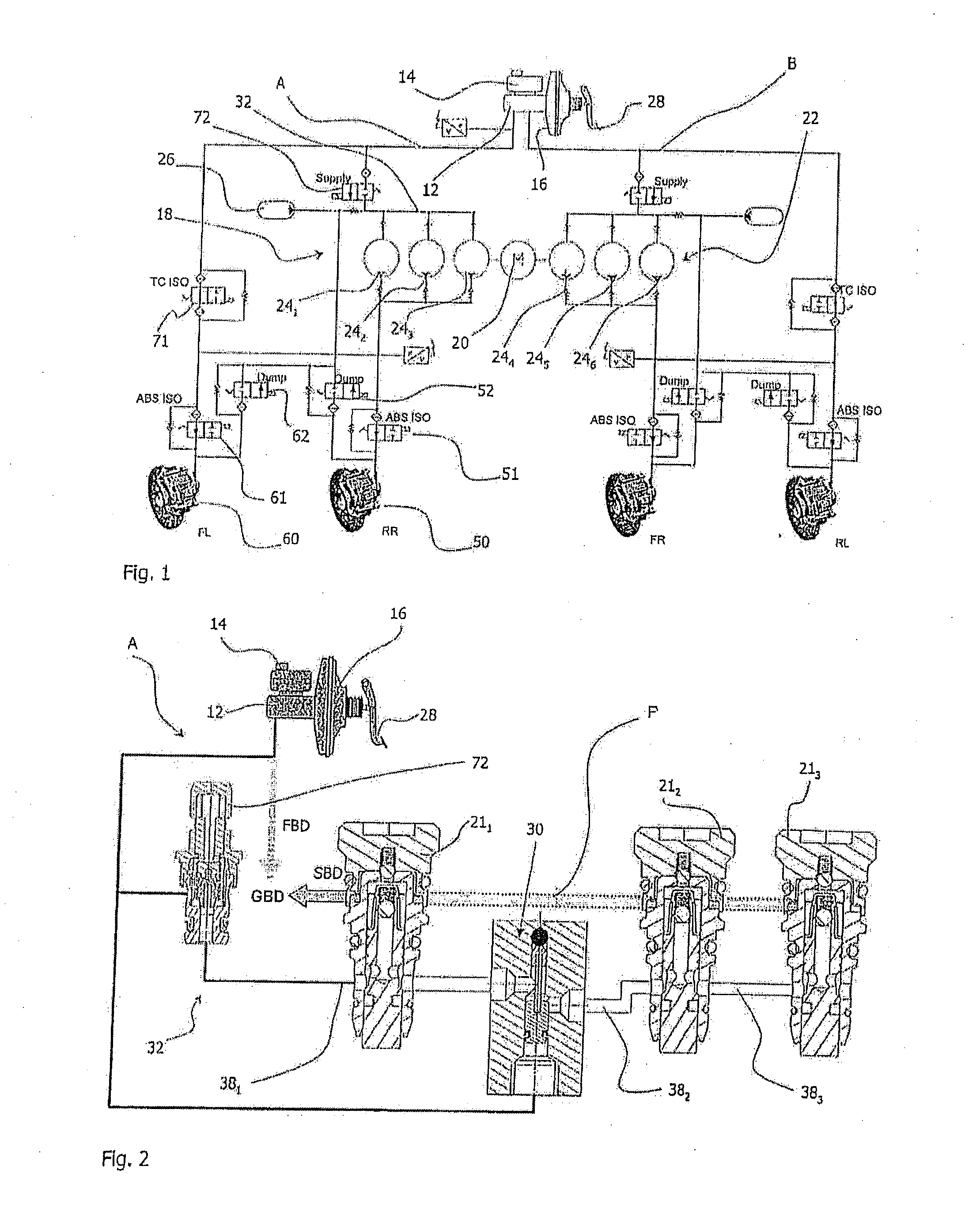
[0025]FIG. 1 shows, as already explained in more detail at the beginning, a vehicle brake system from the prior art which comprises two brake circuits A and B. On actuation of a foot pedal 28 by the driver of the vehicle, a master cylinder 12 delivers a brake fluid from a storage container 14 to the two identical brake circuits A and B. In this way, the respective wheel brakes 50 and 60 are supplied via the brake circuits A and B and a driver brake pressure FBD is built up in the wheel brakes 50 and 60.

[0026]On a signal of the brake system, a pressure generator 18 generates a system brake pressure SBD in the wheel brakes 50 and 60 by driving a multiple-piston pump 22 by means of an actuator 20. In the example illustrated in FIG. 1, the multiple-piston pump 22 comprises six pressure chambers 241, 242, 243, 244, 245, 246 (denoted generally by the reference symbol 24), the pressure chambers 241, 242, 243 being associated with the brake circuit A. The multiple-piston pump 22 is furtherm...


PUM


Abstract

The present invention relates to a pressure generator for a hydraulic vehicle brake system for the regulated generation of a hydraulic brake pressure in a brake circuit, the pressure generator having a multiple-piston pump for delivering a brake fluid with at least two pump pistons and associated pressure chambers, on which the pump pistons act, an actuator for actuating the multiple-piston pump, and a fluid feed line which extends to the pressure chambers and is configured for connection to a storage container, in which a hydraulic fluid is stored. At least one valve is arranged in the fluid feed line and divides the latter into a first section which is arranged upstream of the valve and into a second section which is arranged downstream of the valve, the valve being configured to optionally at least partly shut off or open the second section of the fluid feed line and therefore to control the fluid supply of at least one pressure chamber.

Description

CROSS-REFERENCE TO RELATED APPLICATIONS[0001]This application is a national stage of International Application No. PCT / EP2009 / 002200 filed Mar. 25, 2009, the disclosures of which are incorporated herein by reference in entirety, and which claimed priority to German Patent Application No. 10 2008 019 148.5 filed Apr. 16, 2008, the disclosures of which are incorporated herein by reference in entirety.BACKGROUND OF THE INVENTION[0002]The present invention relates generally to the hydraulic pressure generation in a vehicle brake system. The invention is directed in particular to a pressure generator with a multiple-piston pump.[0003]Modern hydraulic or electrohydraulic vehicle brake systems require reliable pressure generators in order to be able to implement safety-related functions such as preventing locking of the brake or preventing spinning wheels. For this purpose, driver assistance systems, such as anti-lock control (ABS), anti-slip control (ASR) or driving dynamics control and a...

Claims


Application Information

Patent Timeline
Patent Type & Authority Applications(United States)
IPC IPC(8): B60T8/40
CPCB60T8/4031F04B49/225B60T8/4872B60T8/4054
Inventor KOTH, BORIS
Owner LUCAS AUTOMOTIVE GMBH
Why Eureka
Try Eureka