Normal mode noise suppressing circuit

a noise suppressing circuit and normal mode technology, applied in the direction of line-transmission details, current interference reduction, line-transmission, etc., can solve the problems of reducing the normal mode noise, and affecting the quality of communication, so as to reduce the peak value of normal mode noise

Inactive Publication Date: 2007-01-04
SHIMA SEIKI MFG LTD +1
View PDF3 Cites 1 Cited by
  • Summary
  • Abstract
  • Description
  • Claims
  • Application Information

AI Technical Summary

Benefits of technology

[0019] In the normal mode noise suppressing circuit of the invention, the first detection / injection section may incorporate: a first inductance element inserted to the first conductor line at a specific first point; and a second inductance element coupled to the first inductance element. In addition, the injection signal transmission path may include a capacitor for detection and injection that allows the injection signal to pass, and the injection signal transmission path may have an end connected to the first conductor line at a second point different from the first point and the other end connected to the second conductor line. In addition, the second inductance element may be inserted somewhere along the injection signal transmission path, and the node between the injection signal transmission path and the first conductor line may form the second detection / injection section. In this case, the at least one noise suppressing section may further incorporate a peak value reducing section that is provided between the first and second detection / injection sections on the first conductor line and that reduces a peak value of the normal mode noise.
[0020] In the normal mode noise suppressing circuit of the invention, the first detection / injection section may incorporate: a first inductance element inserted to the first conductor line at a specific first point; a second inductance element coupled to the first inductance element; a third inductance element inserted to the second conductor line at a point corresponding to the first point; and a fourth inductance element coupled to the third inductance element. In addition, the injection signal transmission path may include a capacitor for detection and injection that allows the injection signal to pass, and the injection signal transmission path may have an end connected to the first conductor line at a second point different from the first point and the other end connected to the second conductor line at a point corresponding to the second point. Furthermore, the second and fourth inductance elements may be inserted in series somewhere along the injection signal transmission path, and the node between the injection signal transmission path and the first conductor line and the node between the injection signal transmission path and the second conductor line may form the second detection / injection section. In this case, the at least one noise suppressing section may further incorporate a peak value reducing section that is provided between the first and second detection / injection sections on the first and second conductor lines and that reduces a peak value of the normal mode noise.

Problems solved by technology

Consequently, the power transformer circuit develops a ripple voltage having a frequency equal to the switching frequency of the switching circuit, and noise resulting from the switching operation of the switching circuit.
Such a ripple voltage and noise affect other apparatuses.
When the power-line communications are performed, noise emerges on the power line because of the operations of various electric and electronic apparatuses connected to the power line, which causes a reduction in quality of communications, such as an increase in error rate.
The conventional LC filters have a problem that, since the filters have a specific resonant frequency determined by the inductance and the capacitance, a desired amount of attenuation is obtained only within a narrow frequency range.
However, such an inductance element has a problem that the characteristic thereof becomes close to the characteristic of an air-core inductance element, so that the inductance element is increased in size to implement a desired characteristic.
In practice, however, it is impossible that the impedance of the filter circuit is zero.
Because of these facts, the line filter actually fabricated has a problem that it is impossible to effectively reject noise components in a wide frequency range.
In cases where a supply circuit including an anti-harmonic circuit, an inverter control apparatus including a motor drive circuit, or a lighting fixture that performs phase control, for example, is connected to a power line, large normal mode noise emerges on the power line since a switching circuit is directly connected to the power line.
Therefore, it is inevitable to install a filter circuit having a high attenuation factor in such cases, too.

Method used


Image

  • Normal mode noise suppressing circuit
  • Normal mode noise suppressing circuit
  • Normal mode noise suppressing circuit

Examples


Embodiment Construction

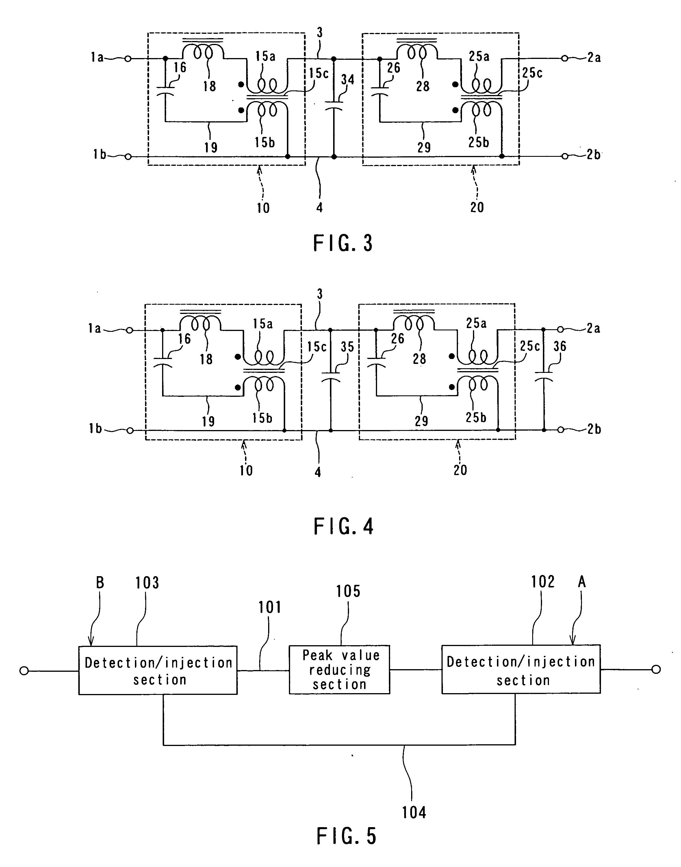
[0036] A preferred embodiment of the invention will now be described in detail with reference to the accompanying drawings. A noise suppressing technique employed in the embodiment of the invention will now be described. A cancellation-type noise suppressing circuit is used in the embodiment. Reference is made to FIG. 5 to describe a basic configuration and operation of the cancellation-type noise suppressing circuit.

[0037] As shown in FIG. 5, the cancellation-type noise suppressing circuit comprises: two detection / injection sections 102 and 103 connected to a conductor line 101 at different points; an injection signal transmission path 104 that connects the two detection / injection sections 102 and 103 to each other through a path different from the conductor line 101; and a peak value reducing section 105 provided between the detection / injection sections 102 and 103 on the conductor line 101.

[0038] Each of the detection / injection sections 102 and 103 performs detection of a signa...


PUM


Abstract

A normal mode noise suppressing circuit comprises: a noise suppressing section (10) provided on conductor lines (3, 4); and a capacitor (31) having an end connected to the conductor line (3) and the other end connected to the conductor line (4). The noise suppressing section (10) comprises: a winding (15a) inserted to the conductor line (3); a winding (15b) coupled to the winding (15a) through a magnetic core (15c); an injection signal transmission path (19); a capacitor (16); and an inductance element (18). The injection signal transmission path (19) has an end connected to the conductor line (3) and the other end connected to the conductor line (4). The winding (15b) and the capacitor (16) are inserted somewhere along the injection signal transmission path (19). The inductance element (18) is inserted to the conductor line (3) at a point between the winding (15a) and the node between the injection signal transmission path (19) and the conductor line (3).

Description

TECHNICAL FIELD [0001] The present invention relates to a normal mode noise suppressing circuit for suppressing normal mode noise transmitted through conductor lines. BACKGROUND ART [0002] Power electronics apparatuses such as a switching power supply, an inverter and a lighting circuit of a lighting fixture incorporate a power transformer circuit for transforming power. The power transformer circuit incorporates a switching circuit for transforming a direct current to an alternating current having rectangular waves. Consequently, the power transformer circuit develops a ripple voltage having a frequency equal to the switching frequency of the switching circuit, and noise resulting from the switching operation of the switching circuit. Such a ripple voltage and noise affect other apparatuses. It is therefore required to provide a means for reducing the ripple voltage and noise between the power transformer circuit and the other apparatuses or lines. [0003] LC filters, that is, filte...

Claims


Application Information

Patent Timeline
Patent Type & Authority Applications(United States)
IPC IPC(8): H04B3/28H03H1/00H03H7/09
CPCH04B3/28H03H7/1758H03H7/09H03H7/427H03H7/1791
Inventor WASAKI, MASARUWASAKI, HITOMISAITOH, YOSHIHIRO
Owner SHIMA SEIKI MFG LTD
Why Eureka
Try Eureka