Multi-level data center consolidated power control

a data center and power control technology, applied in the field of rack level consolidated power, can solve problems such as job affecting power demand, and achieve the effects of preventing or minimizing downtime, stable, reliable power, and preventing or minimizing downtim

Active Publication Date: 2015-04-30
VIRTUAL POWER SYST
View PDF8 Cites 53 Cited by
  • Summary
  • Abstract
  • Description
  • Claims
  • Application Information

AI Technical Summary

Problems solved by technology

Additionally, the schedule for various batch jobs can affect power demands.

Method used


Image

  • Multi-level data center consolidated power control
  • Multi-level data center consolidated power control
  • Multi-level data center consolidated power control

Examples


Embodiment Construction

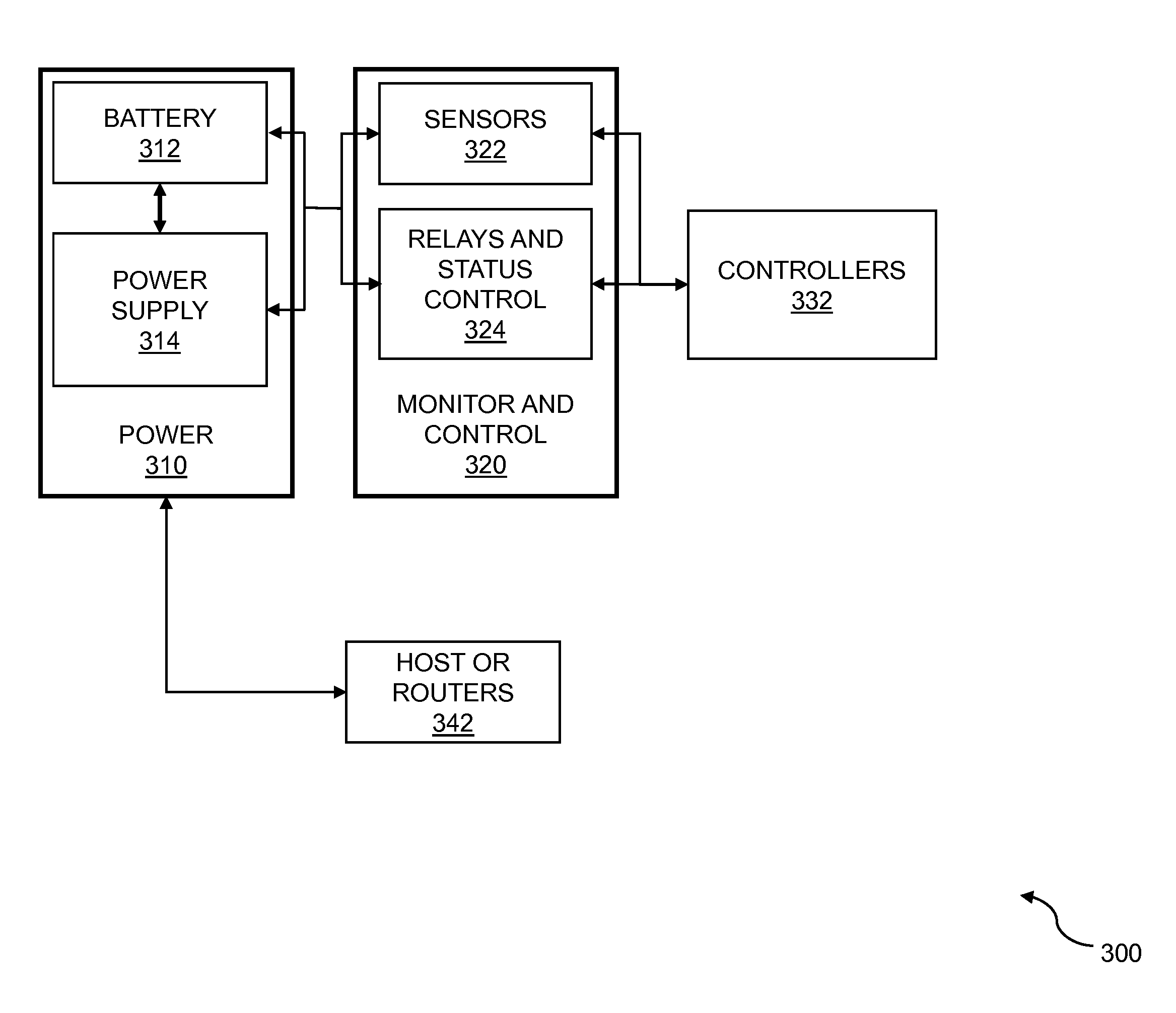
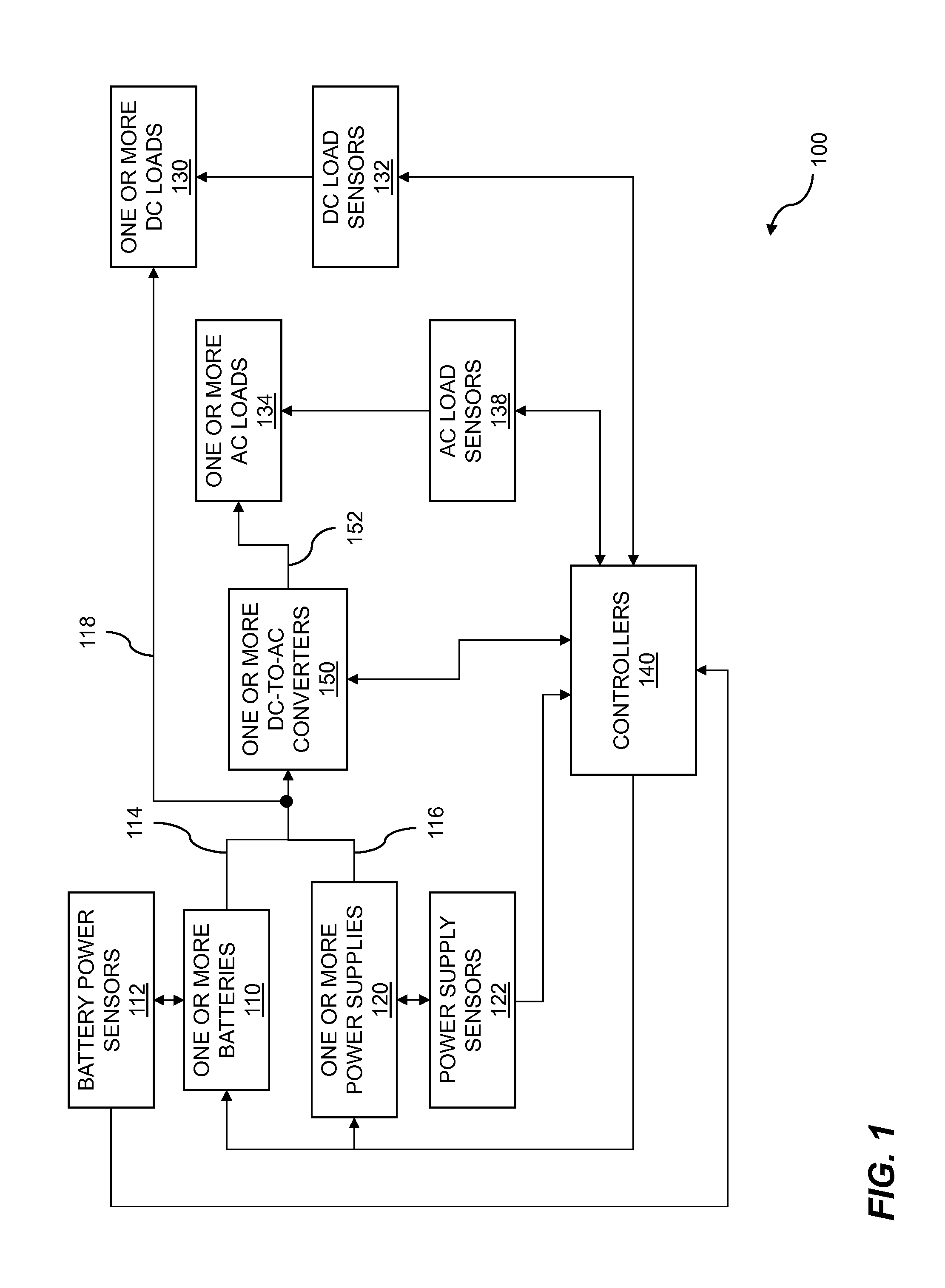
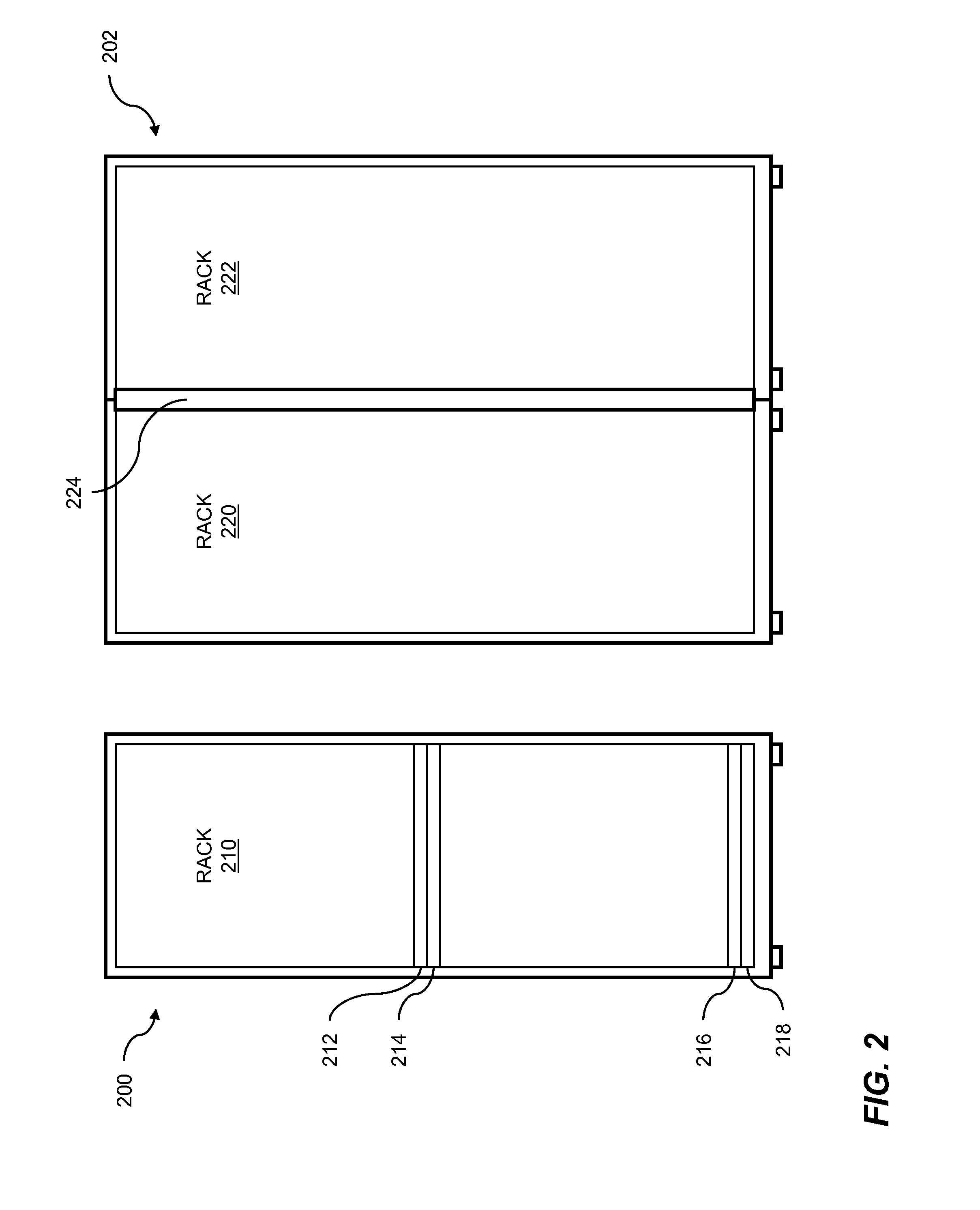
[0018]Data centers, server farms, and other IT processing centers typically utilize standardized racks for the compact mounting of servers, blade components, storage arrays, network interfaces, and other associated equipment. Disclosed embodiments provide distributed power across racks, using one or more controllers to coordinate power from multiple smart power supplies, multiple batteries, and multiple DC-to-AC converters. The smart power supplies are configured to communicate with the controller(s) to provide operating conditions for the smart power supplies to the controllers and receive commands from the controllers specifying real-time changes in needed power, for example. In some embodiments, power is provided to legacy systems which operate at voltages other than those provided by the power supplies. To meet the power requirements of the legacy systems, DC-to-AC power streams can be connected in order to convert current at the power supply and battery voltages to the voltages...


PUM


Abstract

Multi-level data center consolidated power is disclosed. One or more controllers communicate with one or more power supplies and sensors to adapt to dynamic load requirements and to distribute DC-power efficiently across multiple IT racks. The distributed DC-power includes one or more DC-voltages. Batteries can be temporarily switched into a power supply circuit to supplement the power supply during spikes in power load demand while a controller reconfigures power supplies to meet the new demand. In embodiments, one or more DC-to-AC converters handle legacy power loads. The DC-to-AC converters are modular and are paralleled for redundancy. The AC-power is synchronized for correct power flow control. The one or more controllers communicate with the one or more AC-power supplies to dynamically allocate AC-power from the DC-to-AC converters to the multiple IT racks.

Description

RELATED APPLICATIONS[0001]This application claims the benefit of U.S. provisional patent applications “Intelligent Control of Energy and Power Management” Ser. No. 61 / 896,504, filed Oct. 28, 2013, “Intelligent Power Control” Ser. No. 61 / 931,667, filed Jan. 26, 2014, “Dynamic Power Control Through Resource Allocation” Ser. No. 61 / 970,390, filed Mar. 26, 2014, “Dynamic Power Capacity Allocation” Ser. No. 61 / 985,617, filed Apr. 29, 2014, “Multi-Level Data Center Consolidated Power Control” Ser. No. 62 / 029,226, filed Jul. 25, 2014, “Multi-Level Dynamic Power Control Through Capacity Allocation” Ser. No. 62 / 033,618, filed Aug. 5, 2014, “Energy Control Via Power Requirement Analysis and Power Source Enablement” Ser. No. 62 / 047,593, filed Sep. 8, 2014, and “Intelligent Control Of Energy For Rack Level Consolidated Power Systems” Ser. No. 62 / 057,127, filed Sep. 29, 2014. The foregoing applications are each hereby incorporated by reference in their entirety.FIELD OF ART[0002]This application...

Claims


Application Information

Patent Timeline
Patent Type & Authority Applications(United States)
IPC IPC(8): H02J9/06G05B11/01
CPCG05B11/01H02J9/061H02J7/0063H02J9/062H02J7/00712G06F1/30G06F1/3206G06F1/263
Inventor KOUROUSSIS, DENISHURALIKOPPI, RAJEEV P.KENNEDY, RYAN JUSTINNACHBAR, ERICH KARLRAMAMURTHY, SHANKARSAMAL, PRANTHIKSOUNDARARAJAN, RAJARAMSY, ANDREW
Owner VIRTUAL POWER SYST
Why Eureka
Try Eureka