
Control method and device of electromagnetic induction heating equipment and electromagnetic induction heating system

An electromagnetic induction heating and control method technology, which is applied in the control of electromagnetic induction heating equipment and the field of electromagnetic induction heating systems, can solve the problems of high cost of current sensor devices, large PCB area occupation, and zero-crossing detection deviation, so as to improve EMC reliability. performance, reduce control costs, and improve reliability

Active Publication Date: 2022-04-01
GREE ELECTRIC APPLIANCES INC
View PDF12 Cites 0 Cited by
  • Summary
  • Abstract
  • Description
  • Claims
  • Application Information

AI Technical Summary

Problems solved by technology

[0006] The invention provides a control method, device and electromagnetic induction heating system of electromagnetic induction heating equipment, which can solve the problems existing in the prior art including: (1) solve the problem that the traditional method needs a peripheral zero-crossing detection circuit, realize IGBT through software Mains power judgment when it is turned on, to achieve reliable zero-crossing control; (2) Solve the problem of zero-crossing detection deviation caused by external mains cycle fluctuations; (3) Solve the problem of interference when IGBTs are turned on and off, and reduce their startup and shutdown (4) The traditional hardware method is greatly affected by the mains power, and the voltage interference is likely to cause acquisition errors; (5) Solve the interference factors such as harmonics that will be generated during the IGBT working process, resulting in power calculation errors. Current sensor device cost is high, the peripheral circuit is complicated, and the bottleneck problem of PCB area occupation is large

Method used


Image

  • Control method and device of electromagnetic induction heating equipment and electromagnetic induction heating system
  • Control method and device of electromagnetic induction heating equipment and electromagnetic induction heating system
  • Control method and device of electromagnetic induction heating equipment and electromagnetic induction heating system

Examples


Embodiment Construction

[0027] As used herein, the word "first", "second", or the like can be used to describe the elements in the exemplary embodiments of the present invention. These words are only used to distinguish a component and another component, and the inherent characteristics or order of the corresponding elements is not limited by the word. All terms (including techniques or scientific terms) used herein have the same integrated integration of ordinary skill in the art of the present invention, unless otherwise defined. Those terms as defined in the Common Dictionary are explained in the same meaning as the context meaning in the art in the art, and is not interpreted as having an ideal or too formal meaning, unless it is clearly defined in the present invention meaning.

[0028] Those skilled in the art will appreciate that the apparatus and method described herein and the apparatus and methods of the invention are unlimited, and the scope of the invention is limited only by the claims. Feat...


PUM


Abstract

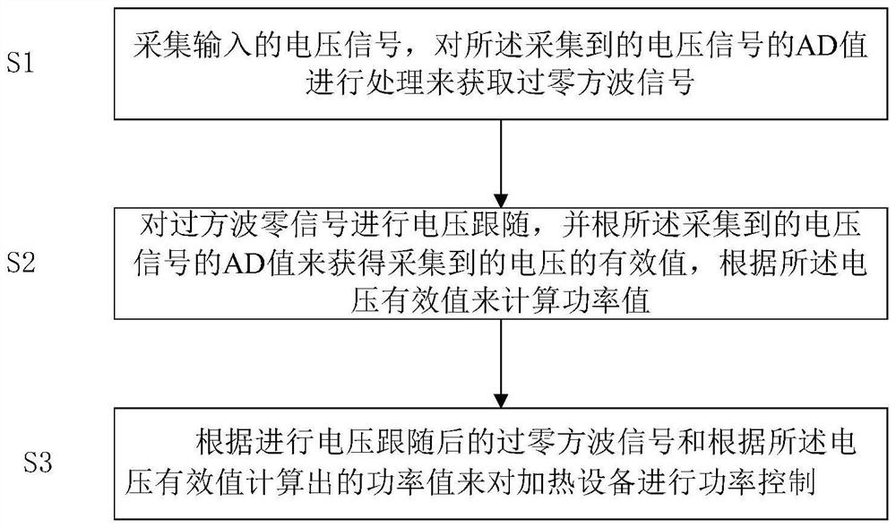
The control method of the electromagnetic induction heating equipment comprises the steps that an input voltage signal is collected, and an AD value of the collected voltage signal is processed to obtain a zero-crossing square wave signal; voltage following is carried out on the square wave zero signal, the effective value of the collected voltage is obtained according to the AD value of the collected voltage signal, and the power value is calculated according to the effective value of the voltage; and performing power control on the heating equipment according to the zero-crossing square wave signal after voltage following and a power value calculated according to the voltage effective value. By adopting the scheme, the reliability of the IGBT is improved, the control interference is reduced, the EMC reliability of the IGBT is improved, the slow fire control cost is effectively reduced, the external interference can be reduced and the stable and reliable power can be obtained through calculation by directly collecting the power frequency voltage waveform data and processing the data in a software form.

Description

Technical field [0001] The present invention relates to the field of intelligent control, and more particularly to control methods, apparatus, and electromagnetic induction heating systems of electromagnetic induction heating equipment. Background technique [0002] IH (induction heat, electromagnetic induction heating) technology As emerging heating technology, the magnetic force generated by current flowing to the heating coil directly heats the entire inner pot, there is no open fire, no exhaust gas, high thermal efficiency, is the focus of future new energy era One of the heating technologies. At present, IH technology has been widely used in industrial and life. IH mainly generates direct current through rectification filtering, direct current generating high-frequency changed magnetic field in electromagnetic coil, using magnetic material, the pot of the magnetic material, cutting the magnetic field in the high frequency magnetic field, and the vortex due to electrothermal ...

Claims


Application Information

Patent Timeline
Patent Type & Authority Applications(China)
IPC IPC(8): H05B6/06H05B6/08
CPCY02B40/00
Inventor 林康桂杨亚鹏左双全李金能陈群
Owner GREE ELECTRIC APPLIANCES INC
Learn More