Temperature Compensated Fiber-Optic Current Sensor

a technology of fiber-optic current and sensor, applied in the direction of electrical testing, measurement devices, instruments, etc., can solve the problems of severe reduction of the performance of the basic sensor configuration, the sensor of fig. 1 may not be suitable for substation applications, and the temperature change cannot be distinguished, so as to reduce the influence of the bend-induced birefringence

Active Publication Date: 2015-04-30
HITACHI ENERGY SWITZERLAND AG
View PDF3 Cites 14 Cited by
  • Summary
  • Abstract
  • Description
  • Claims
  • Application Information

AI Technical Summary

Benefits of technology

[0026]If the looped sensing coil is arranged in a plane, the normal to said plane (i.e. the axis of the coil(s)) is advantageously arranged at an angle of 45°±10° to the principal axes of the retarder. This alignment reduces the influence of the bend-induced birefringence.

Problems solved by technology

However, there are several effects, particularly due to temperature, that can severely reduce the performance of this basic sensor configuration.
As a result, the sensor of FIG. 1 may be unsuited for applications in substations for electric power transmission and distribution where commonly extended temperature ranges of operation are encountered.
Correspondingly, a change of temperature cannot be distinguished from a DC electrical current applied in the enclosed conductor and this sensor configuration cannot be used without temperature stabilization of the Faraday rotator to measure DC electrical currents.
Temperature stabilization on high voltage potential is commonly not a practical option, however.
The method can only be applied for the measurement of alternating currents, because the effects of temperature and direct currents cannot be distinguished.

Method used


Image

  • Temperature Compensated Fiber-Optic Current Sensor
  • Temperature Compensated Fiber-Optic Current Sensor
  • Temperature Compensated Fiber-Optic Current Sensor

Examples


Embodiment Construction

[0049]Definitions

[0050]Terms of the type “substantially circularly polarized light” and similar used herein designates light that can be generated by a superposition of two collinear, coherent, orthogonal, linearly polarized light waves of equal amplitude and a mutual phase shift of 90°+K·180°+Δα, with K being an integer number and Δα being between −30° and +30°, in particular between −15° and 15°. (Δα=0° corresponds to perfect circular polarization.)

[0051]Terms of the type “substantially linearly polarized light” and similar used herein designates light that can be generated by a superposition of two collinear, coherent, orthogonal, linearly polarized light waves of equal amplitude and a mutual phase shift of K·180°+Δα, with K being an integer number and Δα being between −30° and +30°, in particular between −15° and 15°. (Δα=0° corresponds to perfect linear polarization.)

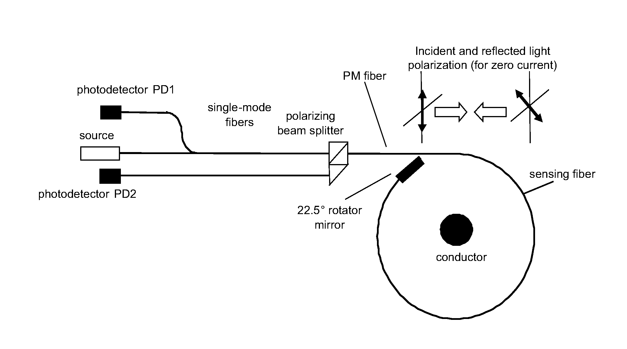
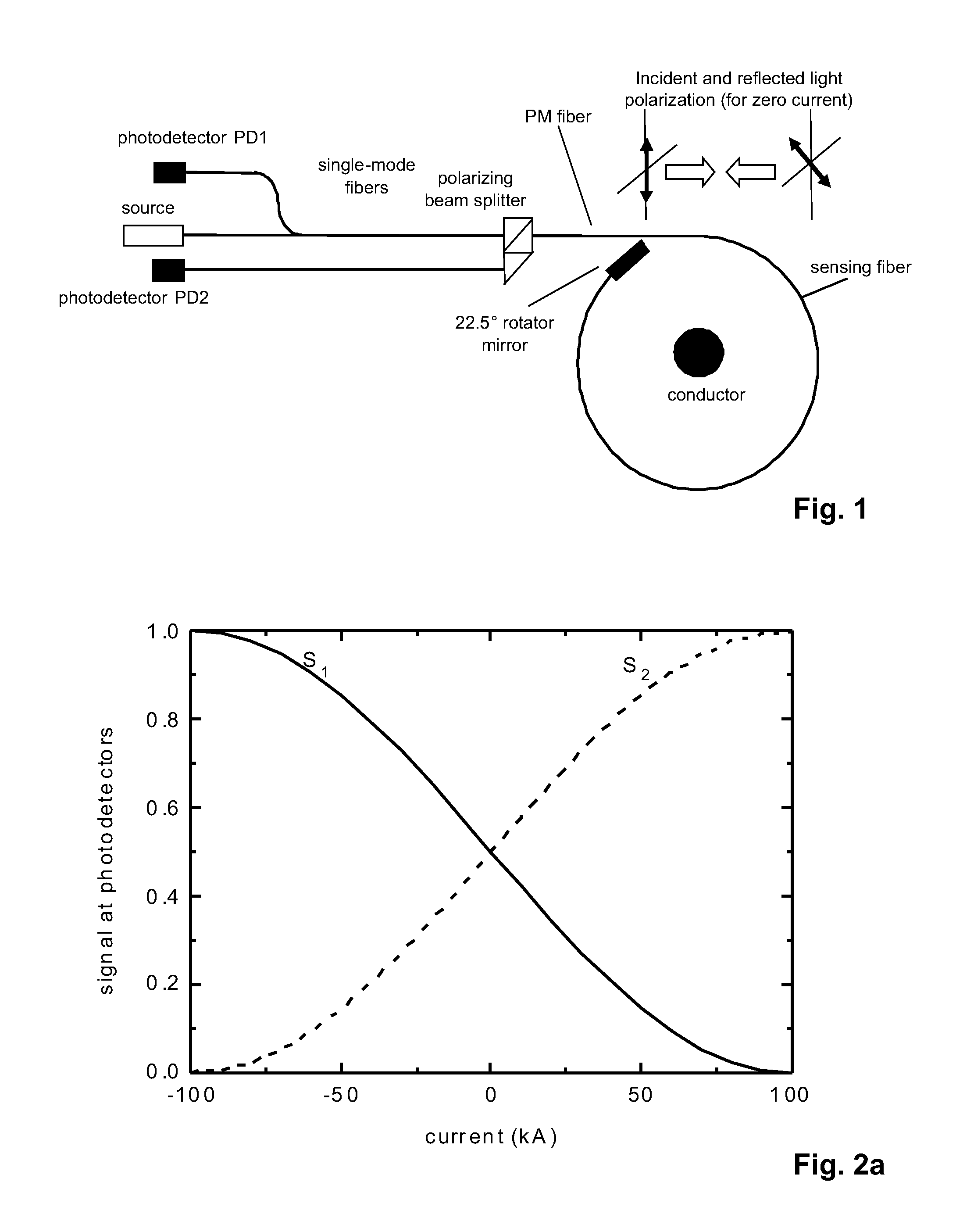
[0052]1. Prior Art Approach

[0053]The basic sensor layout of the sensor underlying the disclosed invention is dep...


PUM


Abstract

In a fiber-optic current sensor, a 22.5° Faraday rotator, which is part of the sensing fiber coil, determines the working point of the sensor. The coil is operated with substantially linearly polarized light or incoherent substantially left and right circularly polarized light waves. In one arrangement, a polarization beam splitter generates two optical signals that vary in anti-phase with changing current. A signal processor determines the current from the two anti-phase signals. Appropriately detuned and oriented fiber-optic half-wave or quarter-wave retarders before the fiber coil are used to reduce or cancel the adverse effects of temperature and bend-induced birefringence on the measurement signal. Moreover, the temperature may be derived from the difference in the bias of the anti-phase signals and may be used to cancel temperature effects in the signal processor.

Description

FIELD OF THE INVENTION[0001]The invention relates to a fiber-optic current sensor having a light source, a linear polarizer, a sensing fiber, a Faraday rotator, a mirror and at least one detector.BACKGROUND OF THE INVENTION[0002]Fiber-optic current sensors commonly rely on the Faraday effect in an optical glass fiber. The fiber forms at least one loop around a conductor that carries the current to be measured. The Faraday effect is observed either as a rotation of the polarization of linearly polarized light or equivalently as differential phase shift between left and right circularly polarized light waves. Sometimes the two sensor versions are referred to as polarimetric and interferometric sensors, respectively. Advantageously, the fiber is operated in a reflective mode, i.e. the light performs a roundtrip through the fiber coil.[0003]The magneto-optic polarization rotation or phase shift is converted to a change in light intensity by means of a polarizer. In order to get a linear...

Claims


Application Information

Patent Timeline
Patent Type & Authority Applications(United States)
IPC IPC(8): G01R19/32G01R15/24
CPCG01R15/246G01R19/32G01R15/247
Inventor MUELLER, GEORGFRANK, ANDREASBOHNERT, KLAUSGU, XUN
Owner HITACHI ENERGY SWITZERLAND AG
Why Eureka
Try Eureka