Antenna structures and methods thereof for selecting antenna configurations

a technology of antenna structure and antenna configuration, applied in the direction of site diversity, differentially intertwined antenna combinations, and discontnuous tuning with seperate pre-tuned circuits, etc., can solve the problems of affecting the system effect, affecting the reception effect, and affecting the transmission effect of the receiver

Inactive Publication Date: 2015-04-30
SKYCROSS INC
View PDF0 Cites 109 Cited by
  • Summary
  • Abstract
  • Description
  • Claims
  • Application Information

AI Technical Summary

Problems solved by technology

If the coupling is, e.g., −10 dB, 10 percent of the transmit power is lost due to that amount of power being directly coupled into the neighboring antenna.
There may also be detrimental system effects such as saturation or desensitization of a receiver connected to the neighboring antenna or degradation of the performance of a transmitter connected to the neighboring antenna.
Thus, while coupling may provide some pattern diversity, it has detrimental system impacts as described above.
The patterns are not uniformly omni-directional and change with frequency due to the changing magnitude and phase of the coupling.
The high isolation between antenna ports restricts interaction between the two amplifiers 1902, 1904, which is known to have undesirable effects such as signal distortion and loss of efficiency.
In handset applications where the antennas are spaced at much less than ¼ wavelength, mutual coupling effects in conventional antennas reduce the radiation efficiency of the array, and therefore reduce the maximum gain achievable.
This large impedance mismatch results in a very high VSWR, shown in FIGS. 27D and 27E, and as a result leads to the desired frequency rejection.
The efficiency-bandwidth trade-off is complex requiring E-M simulation tools for accurate prediction.
In turn, poor efficiency at the antenna translates to less battery life, as the PA must compensate for the loss.
This becomes a problematic as legacy phone antennas support pentaband operation but only bands 5 and band 8.
Such an ideal phase difference, however, may not always be achievable.

Method used


Image

  • Antenna structures and methods thereof for selecting antenna configurations
  • Antenna structures and methods thereof for selecting antenna configurations
  • Antenna structures and methods thereof for selecting antenna configurations

Examples


Embodiment Construction

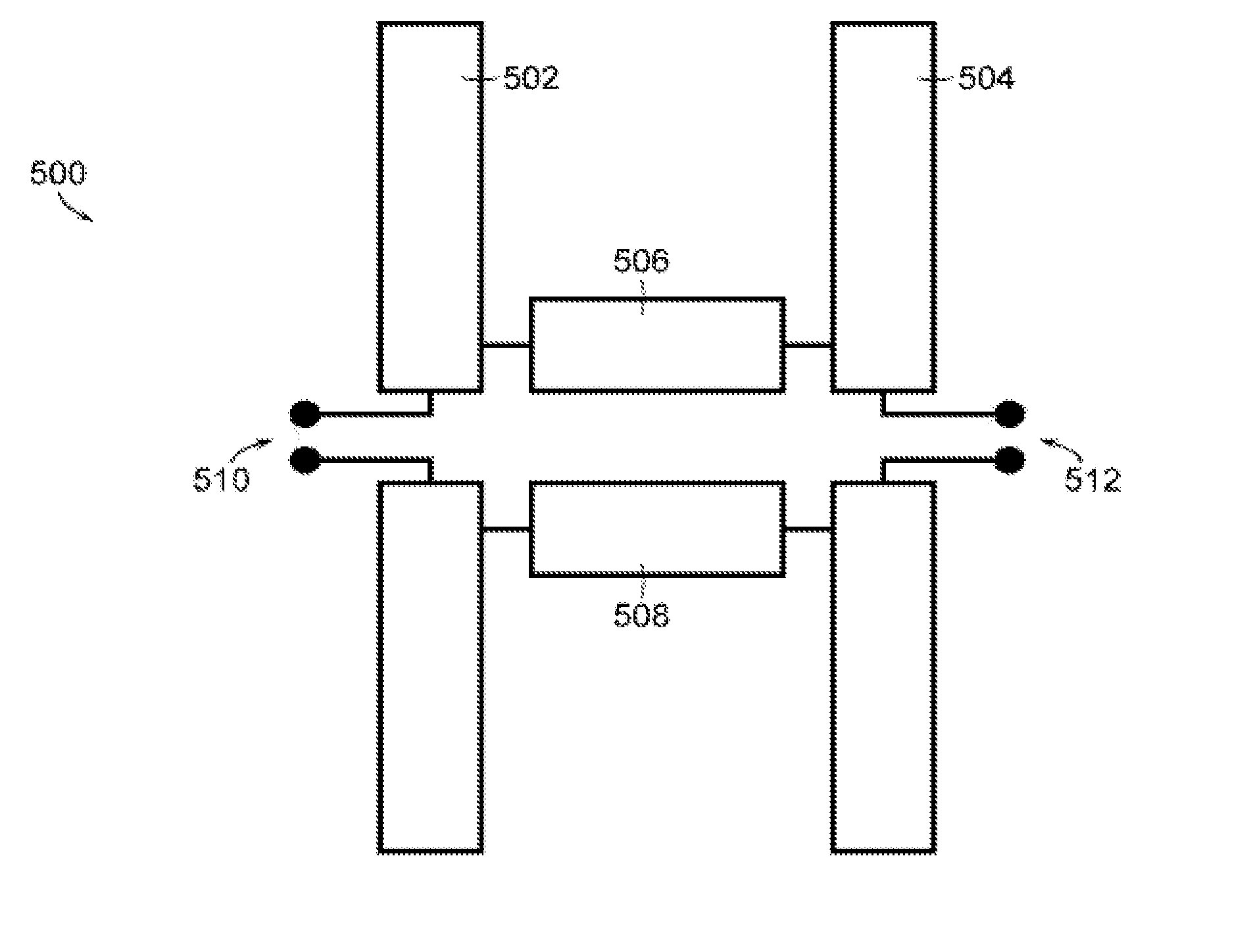
[0082]The subject disclosure describes, among other things, illustrative embodiments for a set of antennas for a communication device forming an antenna configuration having improved performance, where performance is evaluated by determining the envelope correlation coefficient (ECC) of the antenna configuration and antenna isolation. Other embodiments are described in the subject disclosure.

[0083]One embodiment of the subject disclosure includes a method comprising determining, by a communication device comprising a processor, a usage state of the communication device, wherein the communication device comprises a plurality of selectable antennas for engaging in wireless communications; the usage state includes an orientation of the communication device. The method also includes selecting a set of antennas from the plurality of antennas in accordance with the usage state, and obtaining an antenna gain pattern for an antenna in the selected set of antennas. The method further include...


PUM


Abstract

A system incorporating the subject disclosure may include, for example, a method including determining, by a communication device comprising a processor, a usage state of the communication device. The communication device includes selectable antennas, and the usage state includes an orientation of the communication device. The method also includes selecting a set of antennas according to the usage state, and obtaining an antenna gain pattern for an antenna in the selected set of antennas. The method further includes evaluating an expected performance of an antenna configuration corresponding to the selected set of antennas, relative to a performance of an existing antenna configuration. The method also includes initiating usage of the antenna configuration in accordance with improved performance relative to the existing antenna configuration. The antenna configuration comprises a polarization configuration, and the selected set of antennas comprises elements in different planes. Other embodiments are disclosed.

Description

CROSS REFERENCE TO RELATED APPLICATIONS[0001]The present application claims the benefit of priority to U.S. Provisional Application No. 61 / 896,233 filed on Oct. 28, 2013, which is hereby incorporated herein by reference in its entirety.[0002]The present application claims the benefit of priority to U.S. Provisional Application No. 61 / 932,831 filed on Jan. 29, 2014, which is hereby incorporated herein by reference in its entirety.[0003]The present application claims the benefit of priority to U.S. Provisional Application No. 61 / 941,888 filed on Feb. 19, 2014, which is hereby incorporated herein by reference in its entirety.FIELD OF THE DISCLOSURE[0004]The present disclosure relates generally to antenna structures and methods thereof for selecting antenna configurations, particularly configurations with multi-element antennas.BACKGROUND[0005]It is common for communications devices to have multiple antennas that are packaged close together (e.g., less than a quarter of a wavelength apa...

Claims


Application Information

Patent Timeline
Patent Type & Authority Applications(United States)
IPC IPC(8): H01Q3/24H01Q3/34
CPCH01Q3/34H01Q3/24H01Q1/2291H01Q1/38H01Q9/16H01Q9/28H01Q9/30H01Q9/40H01Q9/42H01Q21/0006H01Q21/12H01Q21/29H01Q5/371H01Q5/40H01Q5/48H03J5/244H03J2200/15H04B7/0608H04B7/0691H01Q1/243H01Q9/0442H04B7/0628H04B7/0632H01Q21/28H01Q1/521H04W4/026H04W72/52H04W72/542H01Q13/10H01Q13/103G01R29/10H01Q1/50H01Q5/00H01Q9/145G01R25/00H01Q9/04H01Q21/00H03J5/0245G01R23/02H04W24/08H04W28/12H04W40/12H04B7/0413H04W24/10H04W72/0453H04B7/0417H04W36/18H04B1/38H04B7/0404G01R29/0807H04B1/401H03J5/242H04B1/0053H04W36/08H04W36/32H04W64/003H04W88/08H04B7/024H04W88/06G01C21/20G01S5/0009H01Q5/22
Inventor CHEN, LICAIMI, FRANK M.
Owner SKYCROSS INC
Why Eureka
Try Eureka