
Auto hang tag with radio transponder

a radio transponder and auto-hang technology, applied in the field of radio frequency identification transponders, can solve the problems of interrogator and transponder use tags, limit that have not been completely overcome, etc., and achieve the effect of rapid control of parking facilities and increased range and reliability

Inactive Publication Date: 2005-10-18
WELDON WILLIAMS & LICK
View PDF22 Cites 54 Cited by
  • Summary
  • Abstract
  • Description
  • Claims
  • Application Information

AI Technical Summary

Benefits of technology

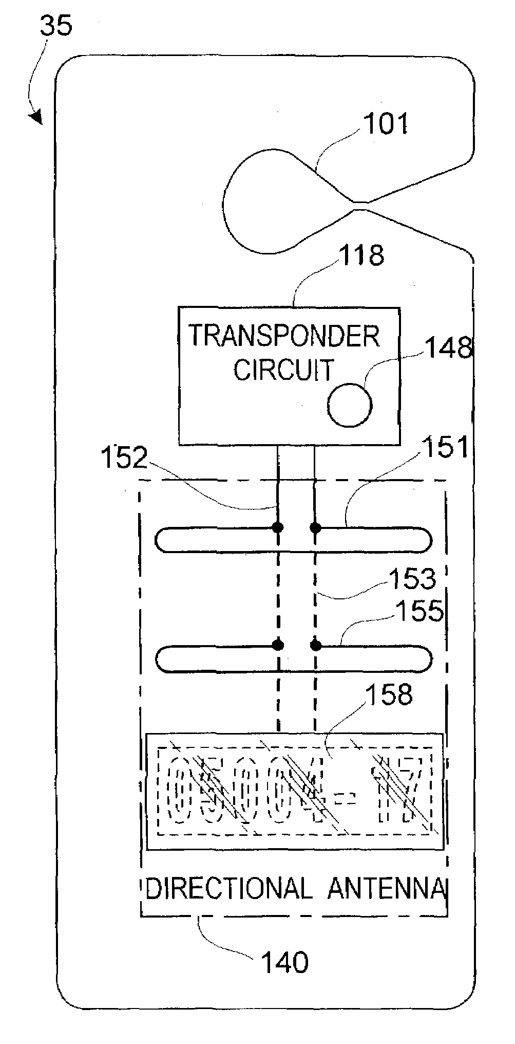
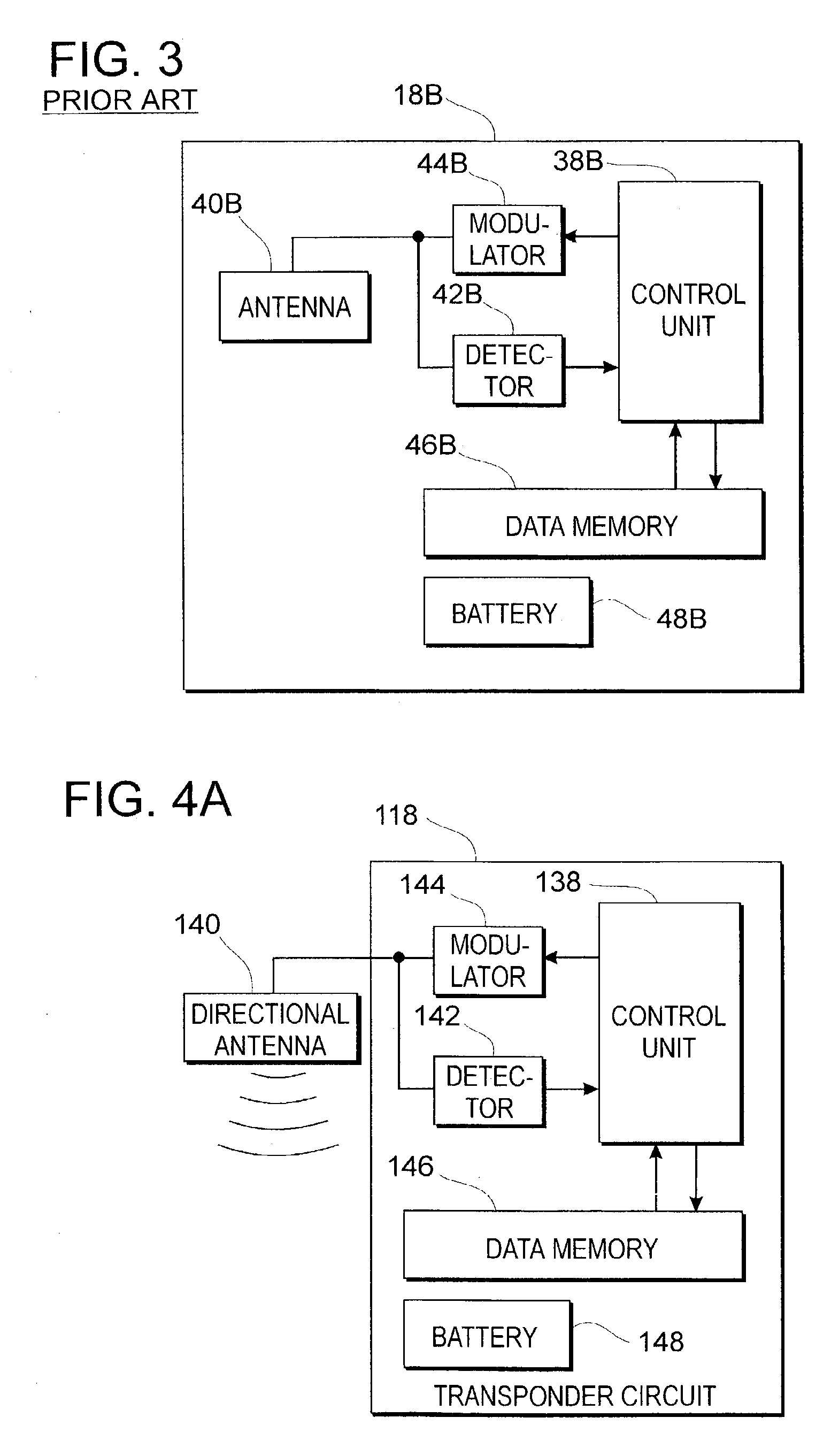
[0010]The present invention relates to systems for parking control or other similar purposes utilizing automobile hang tags incorporating RDIF transponders with directional antennas facilitating remote interrogation of such transponders with increased range and reliability. When employed in a parking control application the detection range for the RFID interrogator and transponder will be at least about 6 meters (about 20 feet) and enables rapid control in monitoring of parking facilities from a moving vehicle employing a transmission path through the back window or the front windshield of parked vehicles. In a system according to the invention customary high gain directional antennas will be employed for the mobile interrogator unit, but the usual omni directional or low gain antennas of RDIF tags are replaced by directional high gain antennas for receiving the transmission from the interrogator and transmitting the reply signal to the interrogator. This is particularly useful in the vehicle parking control application, for in such systems the tags may conveniently be placed in the vehicle in a specified orientation, and the vehicles themselves will be arranged in prearranged parking stalls.
[0011]Thus according to the invention the combined directivity and associated gain for both the interrogator antenna and the transponder antenna are utilized to increase the range and sensitivity for response signals from hang tags in a predetermined preferred direction, while at the same time reducing the likelihood of interference from other hang tags in nearby vehicles. It is important that this system serves to increase the normal range-to-power ratio permitting use of lower power interrogator signals well within regulatory requirements. Suitable directional antennas employed may include Yagi antennas, log periodic antennas, stacked dipole antennas, spiral or slot antennas or other known monodirectional or bidirectional antenna forms. It is preferred that any radio frequencies employed be within the 1,000 megahertz to 10,000 megahertz range; a basic design approach for such antennas may include scaling of television or other communication antennas to smaller size and higher frequency.
[0012]Other known interference reduction techniques may be employed in the controllers software of the system, and, if desired, further interference reduction may be achieved by using radar techniques to maintain a range window corresponding to response signal return time. By this approach transponder return signals from more than a specified distance, 8 meters or 25 feet for example, may be suppressed to eliminate interference from such sources.

Problems solved by technology

While improvements in semiconductor technology to provide microcircuits which are smaller and have lower power requirements have increased the capability of RFID tags and the systems which employ them, there are limitations which have still not been entirely overcome, particularly in the passive type of RFID tags.
Use of such tags where the distance between the interrogator and the transponder is more than a few feet or about one meter presents difficulties.
The amount of power transmitted by the interrogator is subject to regulations as well as practical limitations so that the effect of the well known square-of-the-distance power reduction factor militates against reliable use at longer ranges.
There is an associated problem exacerbated by the low magnitude of the return signal power in that frequently more than one RFID tag is in the area being interrogated, presenting the likelihood that interference between return signals from different tags will adversely affect the reliability of a system.

Method used


Image

  • Auto hang tag with radio transponder
  • Auto hang tag with radio transponder
  • Auto hang tag with radio transponder

Examples


Embodiment Construction

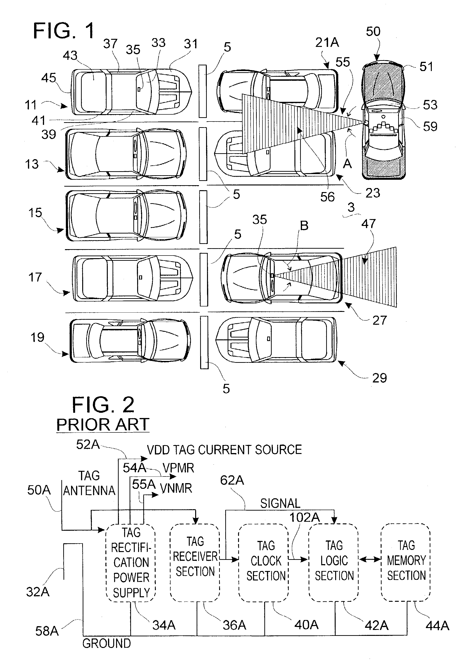
[0031]FIG. 1 shows partially schematically a parking facility and an exemplary form of parking control system incorporating features of the present invention. The parking facility 3 could be of any form but is illustrated having a double row of parking stalls separated by barriers 5.

[0032]Vehicles such as automobile11 are parked front to front on either side of the barriers 5. The vehicles may be of any style and automobile 11 has a common configuration including a vehicle hood 31, front windshield 33, side windows 37 and 39, metal roof 41, back window 43, and rear portion 45. According to the invention a distinctive automobile hang tag 35 is situated near the rear view mirror of automobile 11; such hang tag has a long range, preferably directional propagation, RFID tag incorporated therein. Each of the other vehicles shown, automobiles 13, 15, 17, 19, 21, 23, 27 and 29 will be understood to be generally similar to automobile 11 for the purpose of explaining FIG. 1. It should be und...


PUM


Abstract

There is disclosed an automobile hang tag for use in parking control and the like with an integral radio transponder, together with interrogator apparatus associated therewith in a system for parking control or other purposes. The detection range for the RFID interrogator and transponder is at least about six meters (20 feet) to enable rapid control monitoring of parking facilities from a moving vehicle through the back window or front windshield of parked vehicles. Reliable and trouble-free monitoring of the hang tags in a customary rear view mirror location is facilitated by employing directional antennas in the RFID hang tags, increasing the antenna gain while suppressing false signals and noise and improving the range-to-power ratio for the system. The RFID hang tags may be battery powered but are preferably unpowered RFID transponders. Suitable directional antennas employed may include Yagi antennas, log periodic antennas, stacked dipole antennas, spiral or slot antennas or other monodirectional or bidirectional antennas, preferably those suitable for selected frequencies within the 1,000 megahertz to 10,000 megahertz range.

Description

CROSS REFERENCE TO RELATED APPLICATIONS[0001]Not Applicable.STATEMENT REGARDING FEDERALLY SPONSORED RESEARCH[0002]Not Applicable.BACKGROUND OF THE INVENTION[0003]This invention relates to the field of radio frequency identification transponders (RFID tags), and particular applications thereof involving vehicle identification and parking control systems.[0004]RFID tags receive RF electromagnetic radiation from an interrogating transmitter and return information recorded in the tag to a receiver and computer which is usually associated with the interrogator transmitter.[0005]RFID tags can and have been used in many ways for locating or identifying tagged objects including animals, people, vehicles, or other objects either stationary or mobile. Usually the RFID tag returns distinctive information from the particular tag which may be variable or invariable in nature.[0006]As shown in U.S. Pat. No. 3,098,971 to R. M. Richardson, it has long been proposed that the power necessary to trans...

Claims


Application Information

Patent Timeline
Patent Type & Authority Patents(United States)
IPC IPC(8): G08G1/017
CPCG06K19/07749G06K19/07786G08G1/017H01Q1/2208H01Q1/38H01Q9/28
Inventor WALCOTT, JR., JAMES D.SNOW, JERRY
Owner WELDON WILLIAMS & LICK
Learn More