Surgical Marker and Cap

a marker and cap technology, applied in the field of surgical markers, can solve the problems of difficult to locate the nib, less accurate mapping points, and surgeons cannot see the targeted tissue directly, so as to reduce the evaporation of ink, increase the surface area of the nib and the absorbent fiber block, and reduce the effect of evaporation

Inactive Publication Date: 2015-04-30
NICHIPORENKO IGOR
View PDF9 Cites 10 Cited by
  • Summary
  • Abstract
  • Description
  • Claims
  • Application Information

AI Technical Summary

Benefits of technology

[0032]The absorbent fiber block can have a dimple formed therein. The dimple is configured to receive a tip of a nib of the marker when the enclosure receives the marker. When the tip is seated in the dimple, the amount of surface area of the nib and the absorbent fiber block that are in contact with each other is increased. The increased surface area increase diffusion of ink and limits evaporation of ink from the nib.
[0033]To secure the absorbent fiber block within the cap, the opening of the enclosure can include an inner proximal abutment. That is, the proximal abutment is proximal to the absorbent fiber block. The inner proximal abutment narrows the opening in the cap to a width that is narrower than a width of the absorbent fiber block. A distal plug can be placed on the cap. The absorbent fiber block is inserted via the distal end of the cap. Once inserted, the distal plug is placed on the cap to close the distal end of the cap and to secure the absorbent fiber block between the cap and the inner proximal abutment.

Problems solved by technology

A disadvantage of laparoscopic surgery is that the surgeon cannot see the targeted tissue directly.
However, the mapped points are only mapped on the display, and not on the anatomy.
As the patient and or endoscope move with respect to each other, the mapped points become less and less accurate.
If the nib is dislodged within a patient, the nib is very difficult to locate.
The surgeon is faced with two undesirable alternatives: leaving the nib within the patient or enlarging the incision to search the patient more closely.
In addition, the ink in the nib of the marker has significant risk of drying because the nib is so small and is not connected to a reservoir.

Method used


Image

  • Surgical Marker and Cap
  • Surgical Marker and Cap
  • Surgical Marker and Cap

Examples


first embodiment

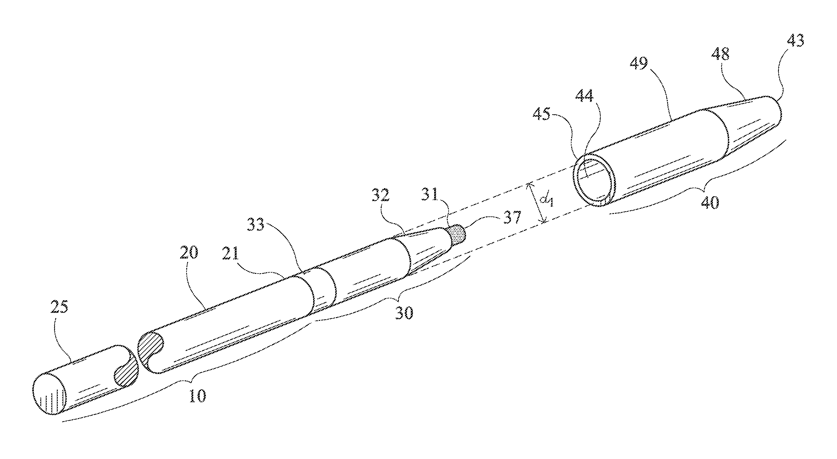
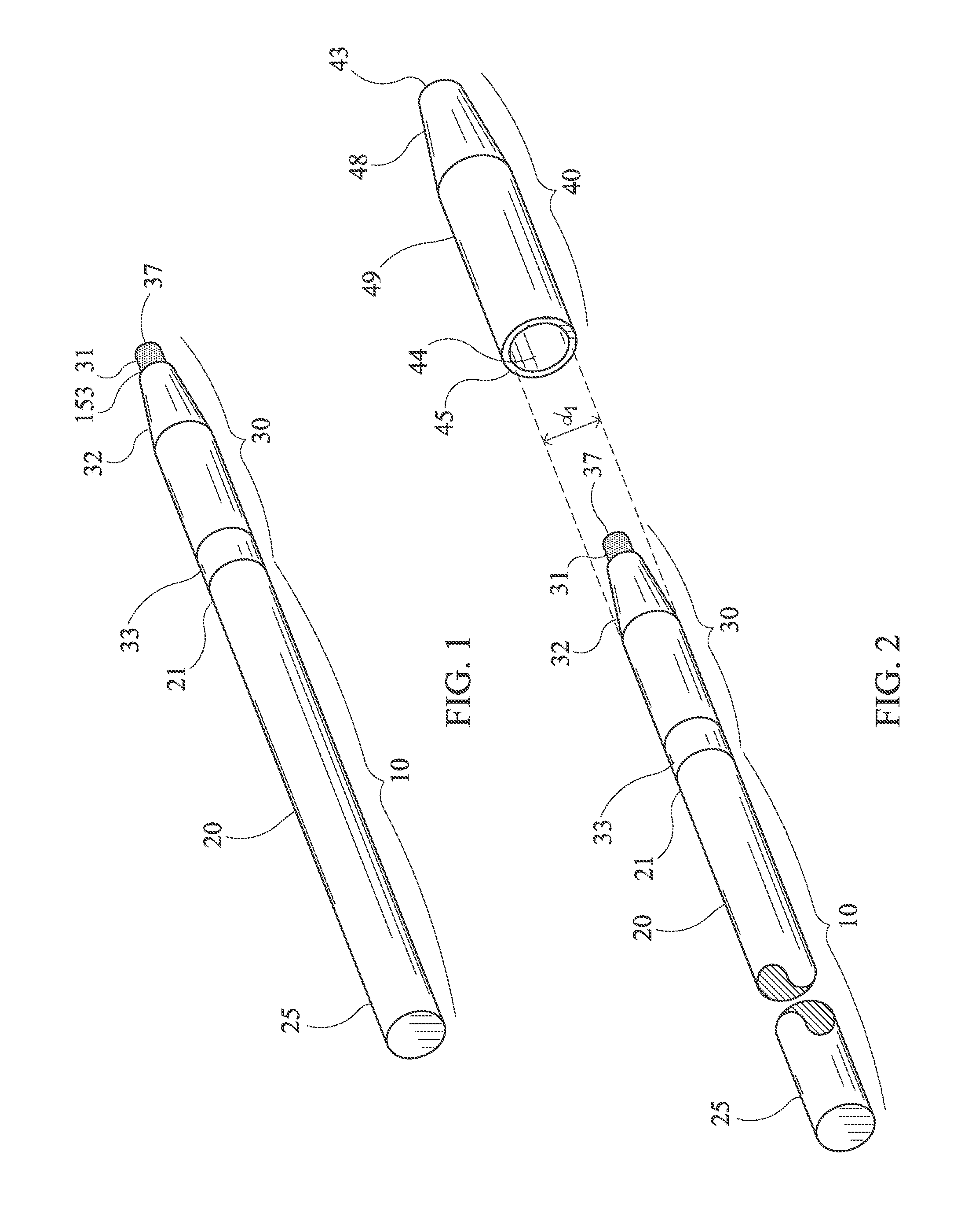
[0054]FIG. 2 shows the surgical marker 30 and rod assembly 10 with a cap 40. The cap 40 is an enclosure with a proximal opening for receiving the tip 37 of the marker 30. The cap 40 has a proximal cylindrical portion 49 and a distal frustoconical portion 48. The distal end 43 of the cap 40 is closed. The cap 40 has an inner tube wall 44. The rod diameter d1 is approximately equal to a diameter of the opening 42. The diameter d1 of the opening in relation to the diameter of the marker should be close enough to allow the cap 40 to receive the surgical mark 30 and form an airtight connection when inserted but still allow the cap 40 to be removed by hand from the surgical marker 30.

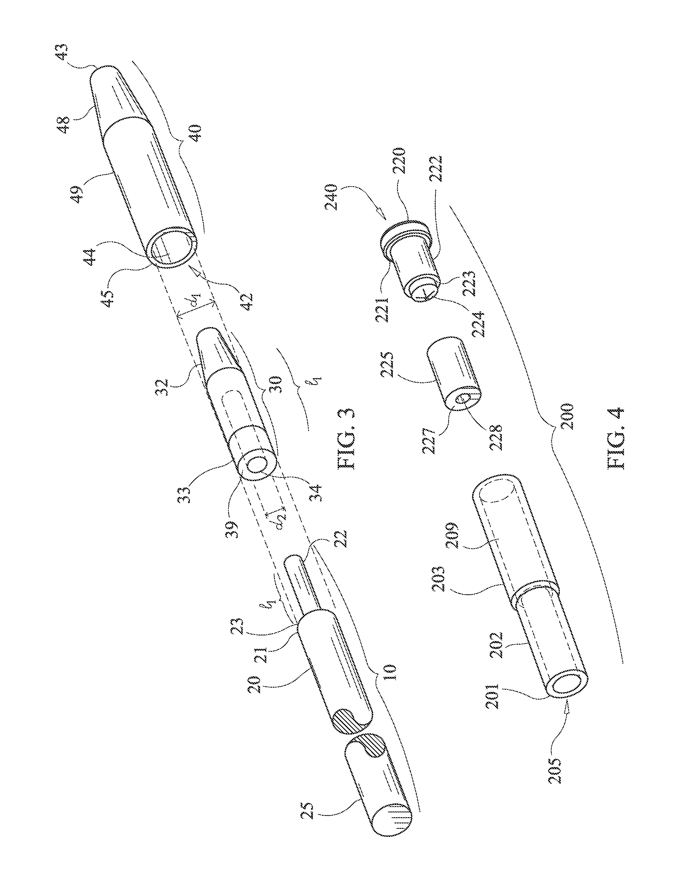
[0055]FIG. 3 shows an exploded view of the rod assembly 10, surgical marker 30, and cap 40 that is shown in FIG. 2. In FIG. 3, the nib 31 is not shown. A peg 22 is disposed on a distal face 23 of the rod 30. In the preferred embodiment, the peg 22 is cylindrical. The peg 22 has a length l1 and a diameter d2. ...

second embodiment

[0061]FIG. 6 shows the cap 200 according to the invention. An enclosure for a marker 30 is formed by a generally cylindrical body that is capped at a distal end and open at a proximal end. A cylindrical, narrow wall 202 is provided at a proximal end of the cap 200. An inner diameter of the narrow wall 202 is sized to fit over an outer diameter of the marker 30. The narrow wall 202 has an opening 205 for receiving the distal end of the marker 30 as shown in FIG. 4. A flange 201 is provided to form an air-right fit when the marker 30 is inserted in the opening 205 of the cap.

[0062]The cap 200 includes an absorbent fiber block 225. The absorbent fiber block 225 is soaked with ink. The absorbent fiber block 225 contacts the nib 31 of the marker 30 when the marker 30 is inserted in the cap 200. Ink diffuses from the absorbent fiber block 225 into the nib 31 to keep the nip 31 moist and inked. As shown in FIG. 11, the absorbent fiber block 225 has a dimple 228 formed in the absorbent fibe...


PUM


Abstract

A surgical marker and cap are useable to mark tissue in laparoscopic procedures. The surgical marker connects to a rod and can be pushed through a cannula to target tissue that is to be marked. The marker can include a decreased length by moving the location of the ink reservoir from the location in a typical marker to a location in the cap. The marker includes a connector to allow it to be easily connected to a rod that contains a peg. The marker is usable in laparoscopic procedures such as the connection of the leads of a diaphragm pacemaker.

Description

CROSS-REFERENCE TO RELATED APPLICATIONS[0001]Not ApplicableSTATEMENT REGARDING FEDERALLY SPONSORED RESEARCH OR DEVELOPMENT[0002]Not ApplicableTHE NAMES OF PARTIES TO A JOINT RESEARCH AGREEMENT[0003]Not ApplicableINCORPORATION-BY-REFERENCE OF MATERIAL SUBMITTED ON A COMPACT DISC[0004]Not ApplicableBACKGROUND OF THE INVENTION[0005]1. Field of the Invention[0006]The invention relates to surgical markers.[0007]2. Description of the Related Art[0008]Laparoscopic surgery, also called minimally invasive surgery (MIS), bandaid surgery, or keyhole surgery, is a surgical technique in which operations in the abdomen are performed through small incisions (usually 0.5-1.5 cm) as opposed to the larger incisions needed in traditional laparotomy.[0009]Laparoscopic surgery provides a number of advantages to the patient versus an open procedure. These include reduced pain due to smaller incisions and hemorrhaging, and shorter recovery time.[0010]A disadvantage of laparoscopic surgery is that the surg...

Claims


Application Information

Patent Timeline
Patent Type & Authority Applications(United States)
IPC IPC(8): A61B19/00
CPCA61B19/44A61B90/39A61B2090/395
Inventor NICHIPORENKO, IGOR
Owner NICHIPORENKO IGOR
Why Eureka
Try Eureka