Substrate transfer apparatus and thin film deposition apparatus having the same

a transfer apparatus and substrate technology, applied in the direction of vacuum evaporation coating, conveying devices, transportation and packaging, etc., can solve the problems of unfavorable change of carrier speed, vibration of carriers, and inability of magnetic levitation units to accurately control carriers, so as to reduce or effectively prevent carriers from being vibrated , the effect of substrate transfer apparatus

Inactive Publication Date: 2015-05-07
SAMSUNG DISPLAY CO LTD
View PDF11 Cites 346 Cited by
  • Summary
  • Abstract
  • Description
  • Claims
  • Application Information

AI Technical Summary

Benefits of technology

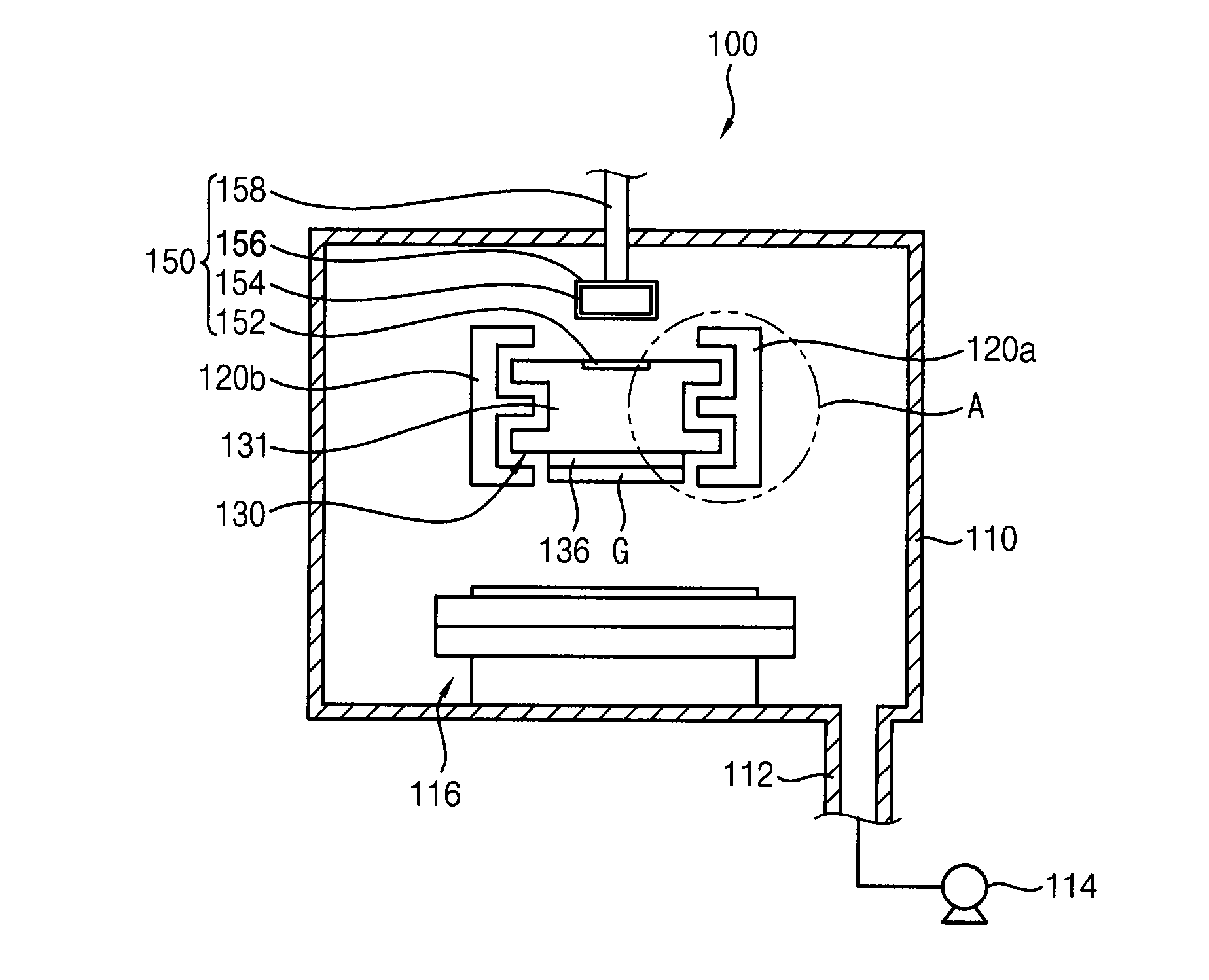
[0006]Processing chambers of a thin film deposition apparatus having the inline type may be arranged in series. In the series arrangement of the processing chambers, a substrate transfer apparatus may be employed to the thin film deposition apparatus for transferring a substrate to each of the process chambers. The substrate transfer apparatus may be divided into a contact type and a non-contact type in accordance with a transferring method of the substrate. The substrate transfer apparatus having the contact type may cause pollution due to particles generated while transferring the substrate (e.g., pollution of a substrate, pollution of a clean room). Alternatively, the substrate transfer apparatus having the non-contact type may solve the pollution, damage to parts of the substrate transfer apparatus caused by a friction and a noise, so that the substrate transfer apparatus having the non-contact type has been researched and developed.
[0008]One or more exemplary embodiment provides a substrate transfer apparatus capable of accurately and sequentially transferring a substrate.
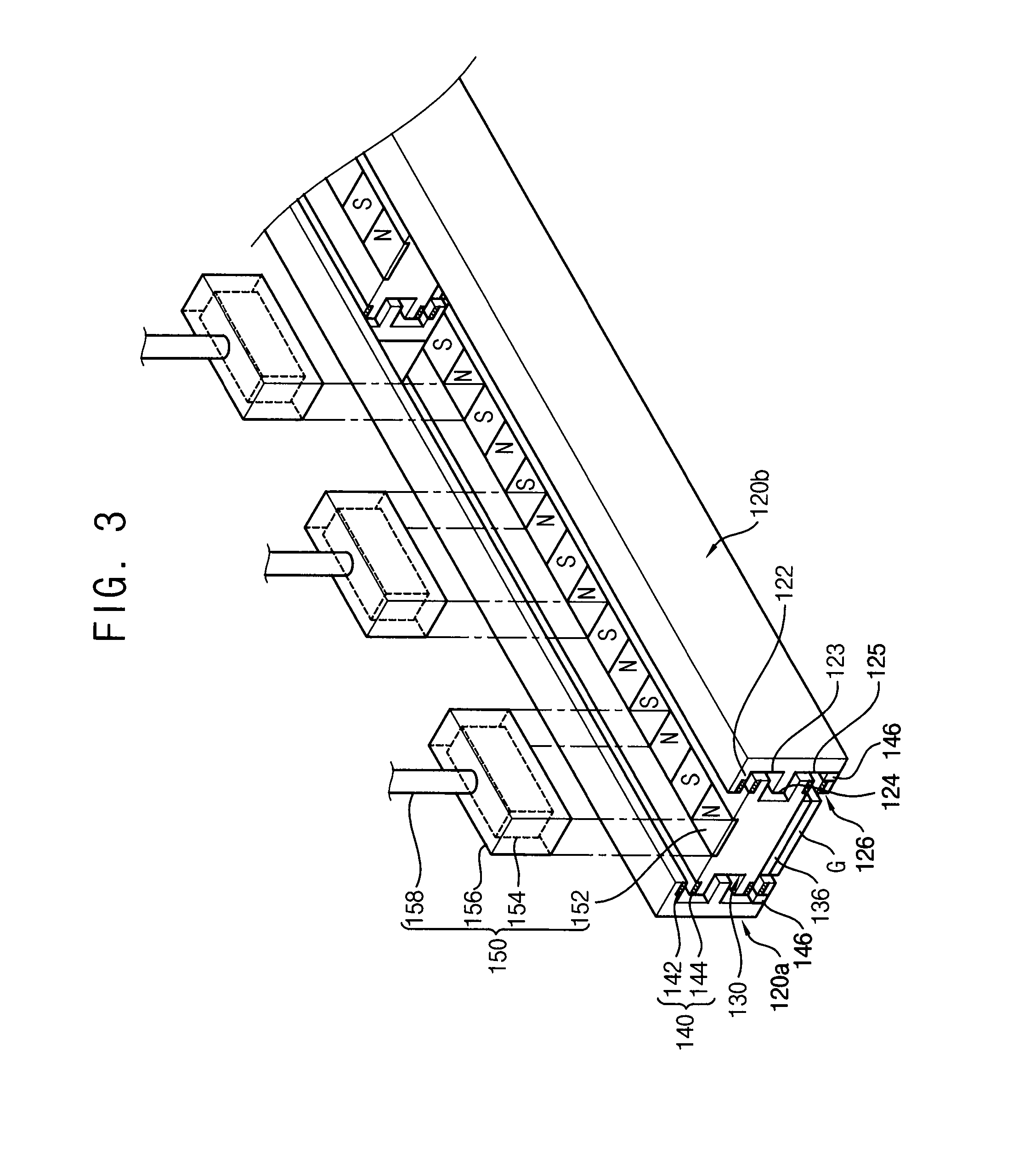
[0030]Therefore, in one or more exemplary embodiment of a substrate transfer apparatus and a thin film deposition apparatus having the substrate transfer apparatus, the substrate transfer apparatus includes the magnetic levitation unit which is configured to magnetically levitate the carrier with respect to the guide rail and the transferring unit which transfers the carrier, both in the chamber selectively having the vacuum state or the atmospheric pressure state. Accordingly, the substrate transfer apparatus may accurately and sequentially transfer the substrate. That is, the substrate transfer apparatus may reduce or effectively prevent the carrier from being vibrated, and the substrate transfer apparatus may reduce or effectively prevent a speed of the carrier from being changed. As a result, the substrate transfer apparatus may efficiently transfer the substrate.
[0031]In addition, the thin film deposition apparatus may transfer the substrate to each of the chambers (e.g., processing chambers having the vacuum state) using the substrate transfer apparatus. As a result, the thin film deposition apparatus may uniformly deposit a thin film on the substrate.

Problems solved by technology

The substrate transfer apparatus having the contact type may cause pollution due to particles generated while transferring the substrate (e.g., pollution of a substrate, pollution of a clean room).
However, the magnetic levitation unit may levitate the carrier using a permanent magnet, so that the magnetic levitation unit may not accurately control the carrier.
That is, the carrier may be vibrated and / or a speed of the carrier may be undesirably changed while magnetically levitating the carrier.
That is, the substrate transfer apparatus may reduce or effectively prevent the carrier from being vibrated, and the substrate transfer apparatus may reduce or effectively prevent a speed of the carrier from being changed.

Method used


Image

  • Substrate transfer apparatus and thin film deposition apparatus having the same
  • Substrate transfer apparatus and thin film deposition apparatus having the same
  • Substrate transfer apparatus and thin film deposition apparatus having the same

Examples


Embodiment Construction

[0040]The invention is described more fully hereinafter with reference to the accompanying drawings, in which exemplary embodiments of the invention are shown. This invention may, however, be embodied in many different forms and should not be construed as limited to the exemplary embodiments set forth herein. Rather, these embodiments are provided so that this disclosure will be thorough and complete, and will fully convey the scope of the invention to those skilled in the art. In the drawings, the size and relative sizes of layers and regions may be exaggerated for clarity.

[0041]It will be understood that when an element or layer is referred to as being “on,”“connected to” or “coupled to” another element or layer, the element or layer can be directly on, connected or coupled to another element or layer or intervening elements or layers. In contrast, when an element is referred to as being “directly on,”“directly connected to” or “directly coupled to” another element or layer, there...


PUM

PropertyMeasurementUnit
spacing distanceaaaaaaaaaa
magnetic levitation forceaaaaaaaaaa
momentumaaaaaaaaaa

Abstract

A substrate transfer apparatus includes a guide rail, a carrier, a magnetic levitation unit, and a transferring unit. The guide rail is in a vacuum evacuable chamber. The carrier may carry a substrate and may be linearly movable along the guide rail. The magnetic levitation unit is configured to generate a magnetic levitation force between the guide rail and the carrier. The transferring unit is configured to generate a momentum for linearly transferring the carrier and includes a plurality of first transferring magnetic material members on an upper surface of the carrier, a plurality of second transferring magnetic material members over the carrier and spaced apart from the first transferring magnetic material members, and a plurality of containers in which the plurality of second transferring magnetic material members is respectively disposed.

Description

[0001]This application claims priority to Korean patent Application No. 10-2013-0134610, filed on Nov. 7, 2013, and all the benefits accruing therefrom under 35 U.S.C. §119, the disclosure of which is hereby incorporated by reference herein in its entirety.BACKGROUND[0002]1. Field[0003]Exemplary embodiments of the invention relate to a substrate transfer apparatus and a thin film deposition apparatus having the substrate transfer apparatus. More particularly, exemplary embodiments of the invention relate to a substrate transfer apparatus for transferring a substrate using a carrier for carrying the substrate thereon and a thin film deposition apparatus having the substrate transfer apparatus.[0004]2. Description of the Related Art[0005]A display device may be manufactured by various processes such as a thin film deposition process, etc. Here, the processes may be performed using a thin film deposition apparatus including process chambers. For example, the thin film deposition appara...

Claims


Application Information

Patent Timeline
Patent Type & Authority Applications(United States)
IPC IPC(8): C23C16/458H01L21/677
CPCH01L21/67709C23C16/4585C23C14/50C23C14/56B60L13/10B65G54/02H01L21/6776
Inventor CHANG, YUN-HOKWON, HYUCK-MOK
Owner SAMSUNG DISPLAY CO LTD
Why Eureka
Try Eureka