Wood pellet burner assembly

a technology of wood pellet burner and burner assembly, which is applied in the direction of combustion process, lighting and heating apparatus, heating types, etc., can solve the problems of reducing the effectiveness of combustion process, needing to handle residual ash and clinker after combustion, and vitrified clinker, etc., and achieves cost saving and space

Inactive Publication Date: 2015-05-07
GRANT STEPHEN WILLIAM JOHN
View PDF3 Cites 3 Cited by
  • Summary
  • Abstract
  • Description
  • Claims
  • Application Information

AI Technical Summary

Benefits of technology

[0027]In a further embodiment of the invention a flame tube is fixed within the enclosed air chamber and which carries a pair of spaced apart transfer apertures, namely a proximal aperture and a distal aperture, each being closed in operating conditions by respective proximal and distal closures; and in which the movable scraper sub-assembly comprises a transversely arranged scraper blade. This allows for various types of scraper sub-assembly to be provided and has the advantage of a totally fixed grate and its flame tube. In one modification of this embodiment of the invention the scraper blade forms the proximal aperture closure. This results in a saving of costs and space.
[0028]In a modification of this latter embodiment the distal aperture closure is formed by a pivotally mounted distal aperture closure on the flame tube. In this modified embodiment the distal aperture closure is opened by the scraper blade and closed by a link mechanism connected to the scraper blade. The advantage of these two embodiments is that the former provides an easy way of providing a distal aperture closure and the latter ensures that in certain instances where a positive closure is required that it may be easily obtained.

Problems solved by technology

One of the major problems with such granular fuel burning boilers is the need to handle the residual ash and clinker after combustion.
Accordingly it has a relatively small amount of vitrified clinker that is formed, however, it is been found to be a serious issue because it tends to form over the apertures in the brazier which in turn reduces the effectiveness of the combustion process.
The problem is that the vitrified clinker does not fall through the brazier and eventually builds up in it.
A further problem that arises with wood pellet boilers generally is that when they are used in domestic situations where the boiler has to be mounted within the building, or living quarters thereof, rather than in, for example, an outhouse separate from the main building there are space considerations.
This problem is exacerbated in small living units such as one or two bedroomed apartments.

Method used


Image

  • Wood pellet burner assembly
  • Wood pellet burner assembly
  • Wood pellet burner assembly

Examples


Embodiment Construction

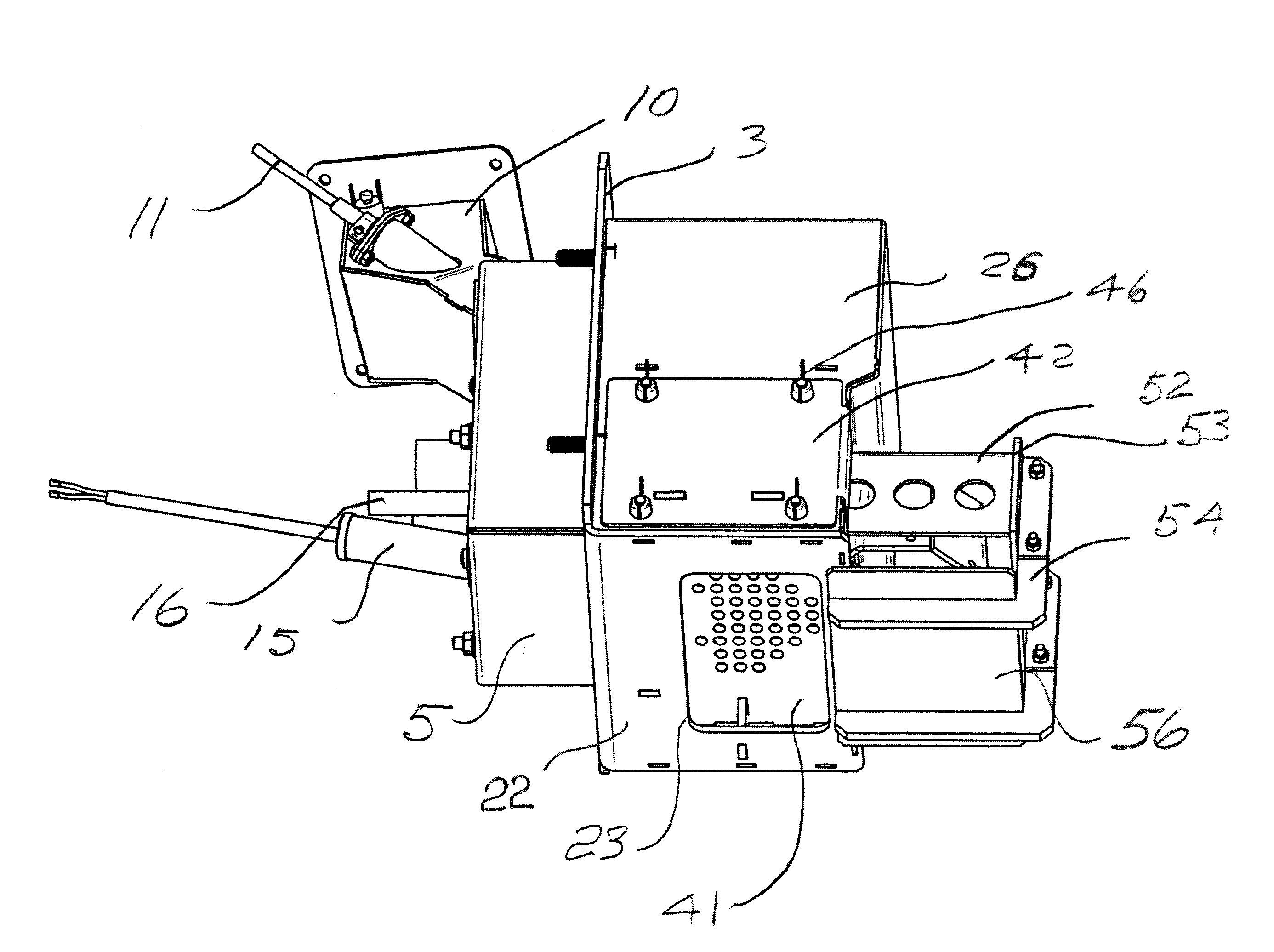
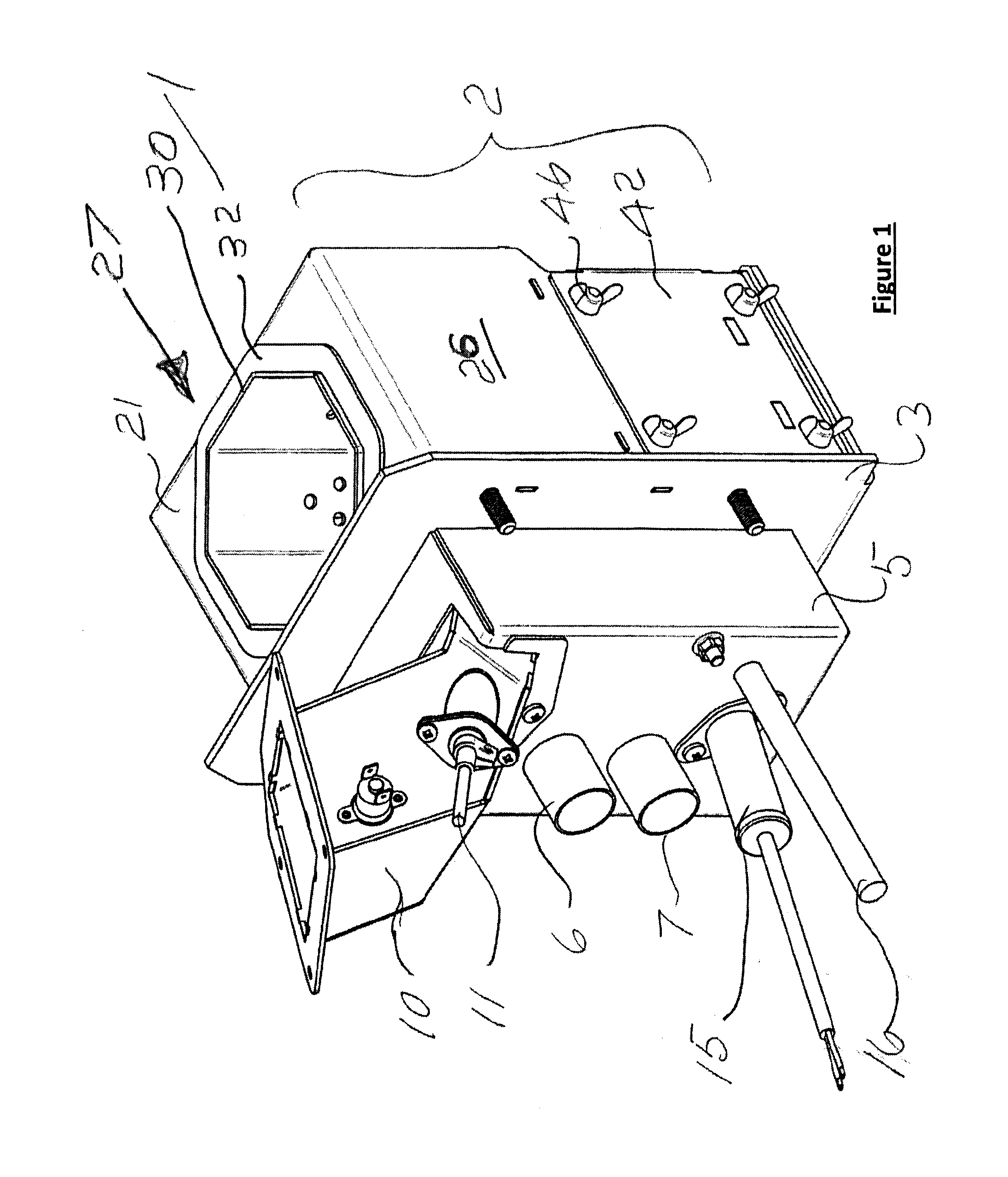
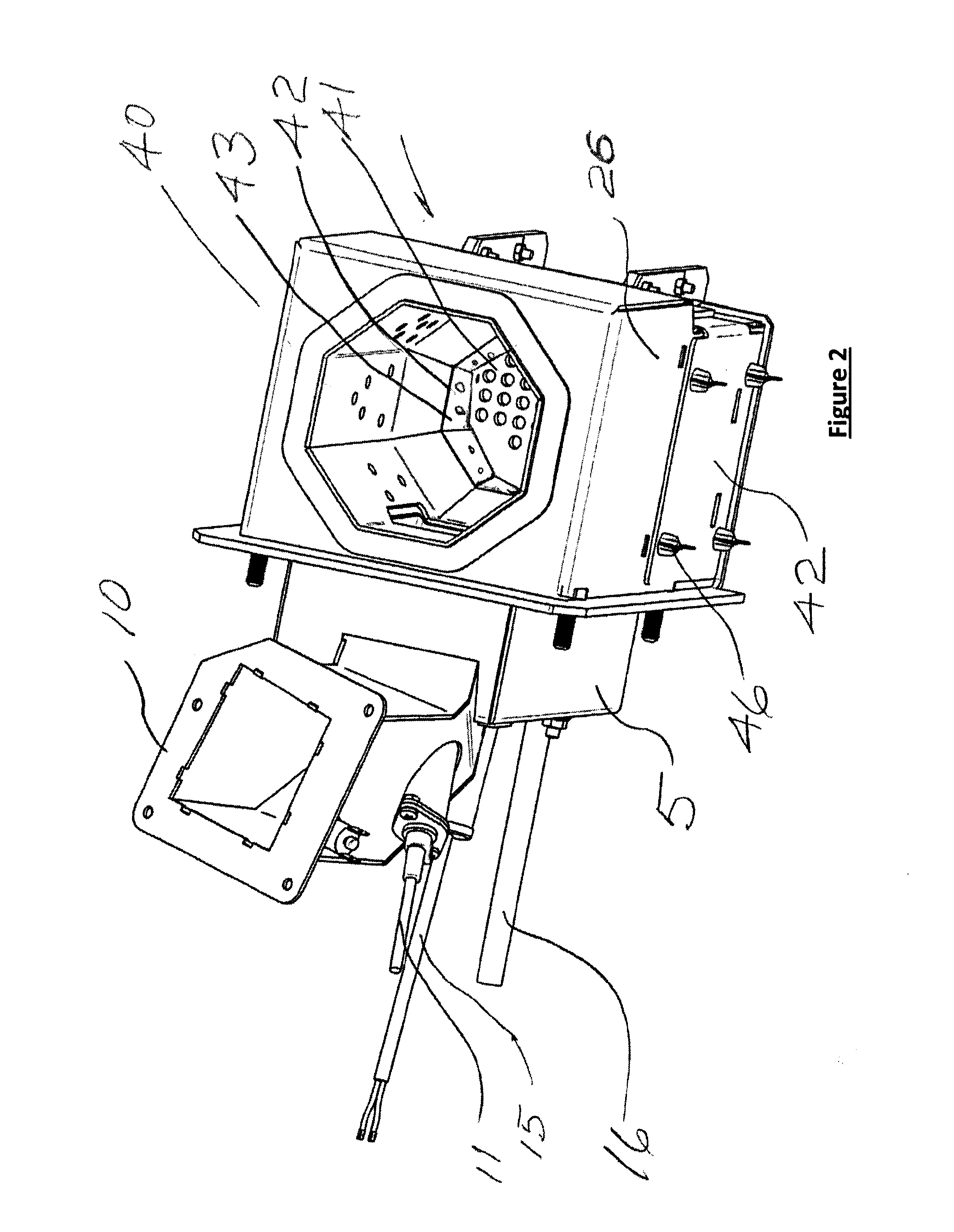
[0054]Referring to FIGS. 1 to 9 of the drawings and initially more particularly to FIGS. 1 to 5, there is provided a wood pellet burner assembly for a wood pellet boiler, indicated generally by the reference numeral 1. The wood pellet boiler is not illustrated. It is a standard enclosed granular fuel burning boiler and indeed the invention is concerned with any wood pellet boiler. The wood pellet burner assembly 1 comprises a main support enclosure 2 for removably mounting within a wood pellet boiler. The main support enclosure 2 is mounted by means of a front wall 3 forming in effect a mounting plate which in turn is part of the main support enclosure 2. There is illustrated a plenum chamber 5 on which in operation there is mounted a modulating fan, not shown, only an inlet 6 and outlet 7 for such a fan is illustrated. There is also illustrated a wood pellet delivery chute 10 mounting a photocell 11 and ignition element and igniter 15 again not illustrated in any detail as all are ...


PUM


Abstract

There is provided a wood pellet burner assembly for a wood pellet boiler, not shown. There is a fixed and easily removable fuel apertured grate mounted above and spaced apart from a base wall forming part of a main support enclosure. A movable scraper subassembly carrying an apertured flame tube is provided which can be moved in and out of the main support enclosure to perform a scraping action on the fixed fuel apertured grate to deliver ash and clinker which have not fallen through the grate during combustion off the grate out of the main support enclosure. This cleaning operation can be carried out at suitable preset time intervals.

Description

[0001]This invention relates a wood pellet boiler, the wood pellet burner assembly being of the type comprising: a main support enclosure for mounting within the wood pellet boiler and for supporting the wood pellet boiler assembly; an enclosed air chamber fed with combustion air from a burner fan; a brazier for reception of wood pellets and a fuel igniter, the brazier and the fuel igniter being housed within the enclosed air chamber.[0002]The invention also relates to any granular fuel burning boiler and a burner therefor. However, since most of the granular fuel used in such boilers and particularly in domestic boilers are wood pellets, for convenience throughout the specification reference has been made almost exclusively to wood pellets and burners therefor.[0003]A considerable amount of the pertinent prior art in respect of this technology is disclosed in various inventions the subject of patent applications and patents designating the present inventor as the inventor.[0004]A c...

Claims


Application Information

Patent Timeline
Patent Type & Authority Applications(United States)
IPC IPC(8): F24B1/02F24B13/02F24B13/00F24B5/02F24B9/00
CPCF24B1/026F24B5/023F24B13/02F24B13/006F24B9/00F23B50/12F23B60/02F24B1/024F23B1/38F23H15/00F23J1/06
Inventor GRANT, STEPHEN WILLIAM JOHN
Owner GRANT STEPHEN WILLIAM JOHN
Why Eureka
Try Eureka