Geothermal loop in-ground heat exchanger for energy extraction

a heat exchanger and geothermal loop technology, applied in the direction of heating fuel, other heat production devices, lighting and heating apparatus, etc., can solve the problems of catastrophic failure, high cost, time-consuming and costly, etc., and achieve the effect of low friction coefficien

Active Publication Date: 2015-05-07
CONTROLLED THERMAL TECH
View PDF13 Cites 26 Cited by
  • Summary
  • Abstract
  • Description
  • Claims
  • Application Information

AI Technical Summary

Benefits of technology

[0010]The naturally occurring hot reservoir can comprise a geothermal water reservoir, which incorporates any subterranean formation containing at least 10 percent water by volume, which may be required to transmit the geothermal heat from the naturally occurring hot reservoir to the outer shell tube casing. If the naturally occurring hot reservoirs do not contain at least 10% water by volume, then a fluid, preferably water, may need to be injected into the reservoir to maintain adequate heat transfer from the reservoir to the outer shell tube casing. In this way, the fluid injected into the reservoir may act as a transportable heat transfer medium in order to more effectively transfer the heat from the reservoir to the outer shell tube casing.
[0060]It may be possible to design a wellbore that houses a submersible pump and an in-ground heat exchanger. Artificial Lift through employing a submersible pump to keep the reservoir fluid pressurized (and keep the solids in solution), however, may assist with elimination of some of the issue that the in-ground heat exchanger of the present invention addresses.

Problems solved by technology

This substantially restricts the reservoir numbers unless reservoir fracturing is employed, which is time consuming and costly and largely unpredictable.
In addition, the open well configuration of both systems suffer from significant well scaling and corrosion which severely limits performance and at times lead to catastrophic failures.

Method used


Image

  • Geothermal loop in-ground heat exchanger for energy extraction
  • Geothermal loop in-ground heat exchanger for energy extraction
  • Geothermal loop in-ground heat exchanger for energy extraction

Examples


Embodiment Construction

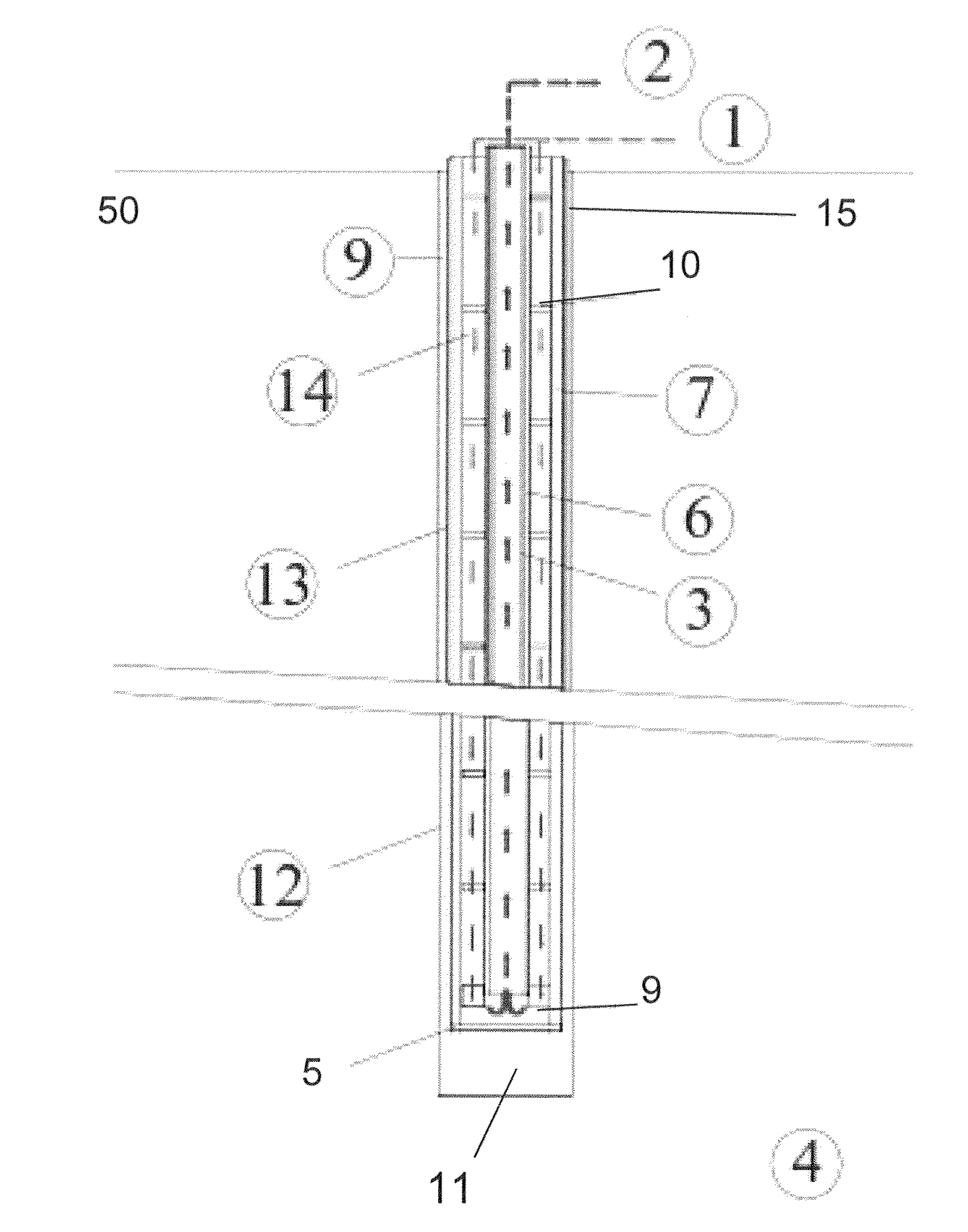
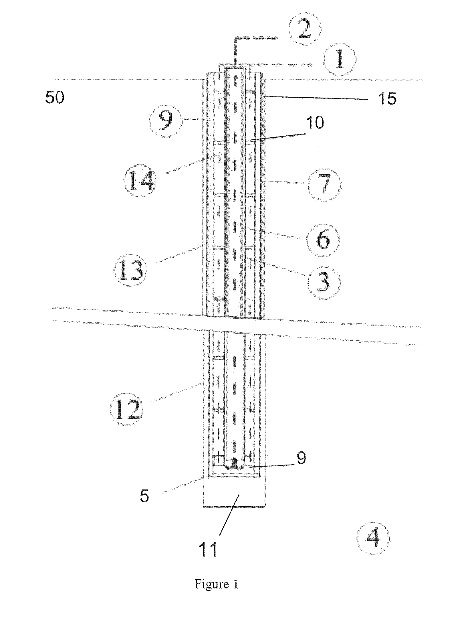
[0085]According to a preferred embodiment of the present invention, a closed loop coaxial heat exchanger assembly is provided.

[0086]FIG. 1 is a sectional side elevation view of the present invention where a wellbore is extending from the surface through to the naturally heated subterranean reservoir, housing the coaxial heat exchanger which is in conductive and convective communication with the reservoir.

[0087]The arrows in FIG. 1 illustrate the working fluid directional flow through the annulus from the injection point above ground level through the hot reservoir where heat is transferred laterally from the reservoir through the casing grout and outer shell of the coaxial heat exchanger to the working fluid. The working fluid continues to the bottom of the heat exchanger and back up through the core of the coaxial heat exchanger to the ground surface where it can be used for power production or heating or cooling and hence closing the loop.

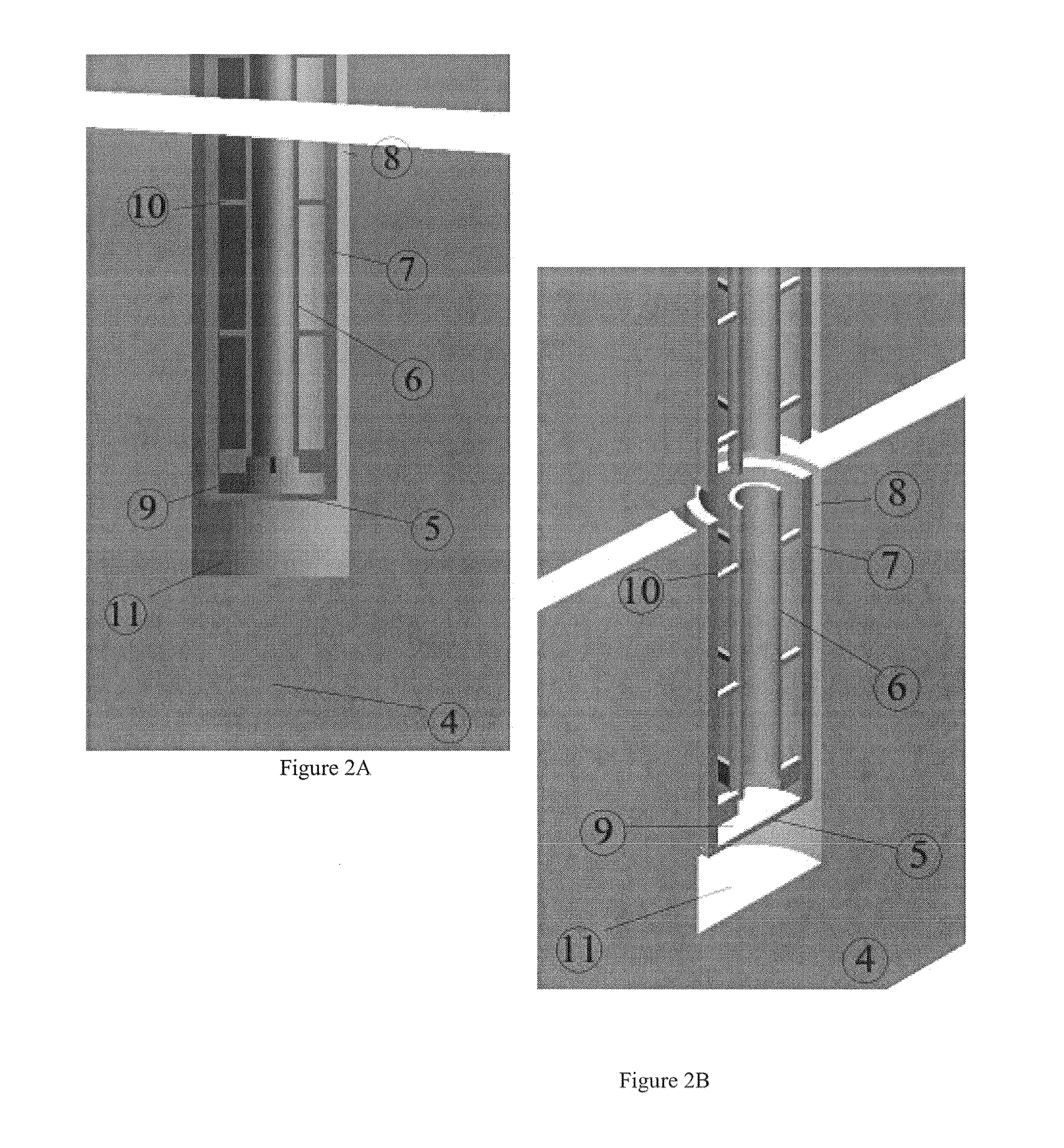
[0088]FIG. 2a is a sectional side elevatio...


PUM


Abstract

A geothermal loop in-ground heat exchanger for energy extraction including an outer tubular casing and an inner tubular portion spaced from the outer tubular casing to define an injection space wherein a working fluid is injected into the injection space at a first temperature, T1 while the heat exchanger is located in a geothermal heat reservoir and the working fluid exits through the inner tubular portion at a second temperature, T2 which is greater than T1.

Description

TECHNICAL FIELD[0001]The present invention relates to geothermal energy devices and systems that extract naturally occurring subterranean geothermal heat from a subsurface formation or reservoir and deliver the heat to the surface where mechanical and or electrical power can be produced through the use of working fluids such as an expanding gas or expanding vapor devices.BACKGROUND ART[0002]The concept and function of geothermal energy systems is known in the art. The basic operation of geothermal energy system requires a “Hot Sedimentary Aquifer” that can be accessed by a deep borehole and the hot fluid (“primary working fluid”) extracted to the surface through cased production wells for heat extraction through an above-ground heat exchanger, the spent aquifer water is pumped back into the reservoir to recharge the reservoir through a separate injection well. The heat removed in the heat exchanger is then used in, e.g. a Rankin Cycle power plant or similar to produce electrical ene...

Claims


Application Information

Patent Timeline
Patent Type & Authority Applications(United States)
IPC IPC(8): F24J3/08F03G7/04
CPCF03G7/04F24J3/081F24T10/17F24T10/20F24T10/30F24T2201/00Y02E10/10
Inventor COLWELL, RODNEY GRAHAME
Owner CONTROLLED THERMAL TECH
Why Eureka
Try Eureka