Self-sensing dielectric elastomer device

Active Publication Date: 2015-05-07
AUCKLAND UNISERVICES LTD
3 Cites 18 Cited by

AI-Extracted Technical Summary

Problems solved by technology

The required external sensors increase the component count and complexity of the actuator.
External sensors do not directly provide any feedback regarding the electrical state of a DED.
When this happens the charge on the DED will be rapidly discharged through the thickness of the membrane 11, generating significant heat and often resulting in catastrophic failure of the DED.
Due to the high voltages necessary for efficient DEDs, implementing capacitive self-sensing is not as simple as applying the capacitive sensing techniques commonly applied in other fields.
However, there are several potential disadvantages to such systems and methods.
Firstly, due to the high voltages typical in DED systems, the prior art methods require relatively expensive high voltage electronic...

Benefits of technology

[0070]Preferably, the feedback is used to cont...

Abstract

The invention provides circuits, systems and methods for dielectric elastomer device (DED) self-sensing. The circuit comprises a first DED coupled or adapted for coupling to a first voltage source (for providing an actuating or priming signal, for example); a current sensor provided in series with the first DED; and an oscillating signal source coupled to the first DED and adapted to cause an oscillation in a voltage across the DED, wherein the oscillating signal source is decoupled from the first voltage source.

Application Domain

Piezoelectric/electrostriction/magnetostriction machinesCurrent/voltage measurement +1

Technology Topic

PhysicsHemt circuits +7

Image

  • Self-sensing dielectric elastomer device
  • Self-sensing dielectric elastomer device
  • Self-sensing dielectric elastomer device

Examples

  • Experimental program(4)

Example

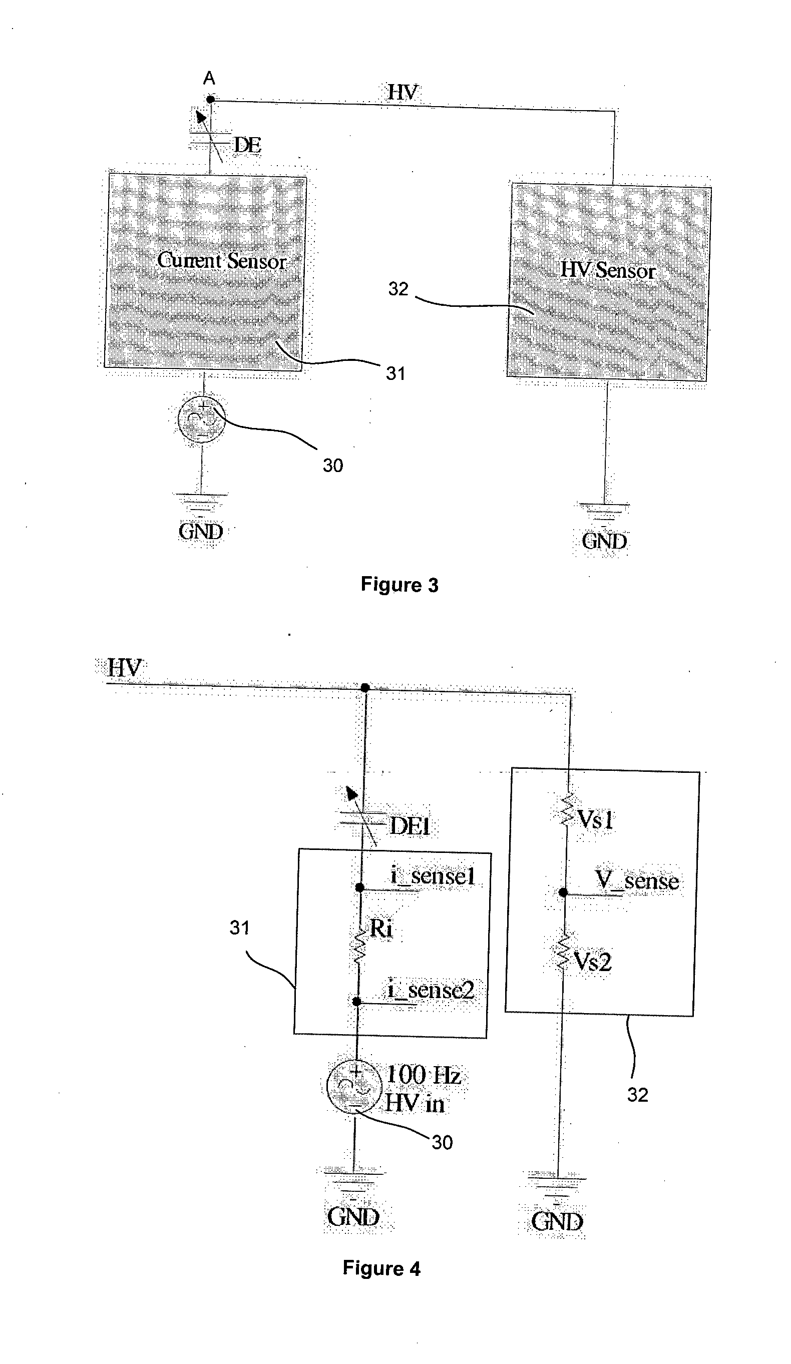
[0090]FIG. 3 a block diagram of a first embodiment of a self-sensing dielectric elastomer device circuit according to the present invention;
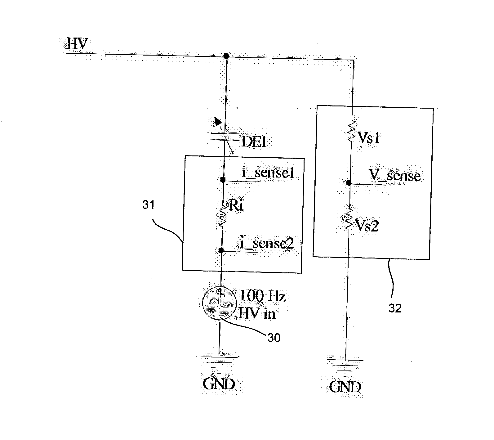
[0091]FIG. 4 is a schematic of the circuit of FIG. 3;

Example

[0092]FIG. 5 is a block diagram of a second embodiment of a self-sensing dielectric elastomer device according to the present invention;
[0093]FIG. 6 is a block diagram of a dielectric elastomer generator system incorporating the circuit of FIG. 5;
[0094]FIG. 7 is a schematic of the system of FIG. 6;
[0095]FIG. 8 shows simulated and estimated capacitance waveforms of the DED in the system of FIG. 7;
[0096]FIG. 9 shows a simulated output voltage waveform of the DED in the system of FIG. 7;

Example

[0097]FIG. 10 is a block diagram of a third embodiment of a self-sensing dielectric elastomer device circuit according to the present invention;

PUM

no PUM

Description & Claims & Application Information

We can also present the details of the Description, Claims and Application information to help users get a comprehensive understanding of the technical details of the patent, such as background art, summary of invention, brief description of drawings, description of embodiments, and other original content. On the other hand, users can also determine the specific scope of protection of the technology through the list of claims; as well as understand the changes in the life cycle of the technology with the presentation of the patent timeline. Login to view more.
Why Eureka
Try Eureka