Radar antenna assembly

a technology for antennas and assemblies, applied in the direction of individually energised antenna arrays, instruments, and reradiation, can solve the problems of many design challenges, high cost of conventional systems, and inability to integrate into the vehicle system, etc., and achieve the effect of reducing reflection

Active Publication Date: 2015-05-07
APTIV TECH LTD
View PDF1 Cites 41 Cited by
  • Summary
  • Abstract
  • Description
  • Claims
  • Application Information

AI Technical Summary

Benefits of technology

[0006]In another embodiment, the assembly includes a pair of impedance transformers interposed between the microstrip patch and the hybrid coupler. The

Problems solved by technology

However, the cost of conventional systems is typically high and integration into the vehicle system is generally complex, due to the need for multiple sensors at multiple locations, currently limiting these systems to o

Method used


Image

  • Radar antenna assembly
  • Radar antenna assembly
  • Radar antenna assembly

Examples


Embodiment Construction

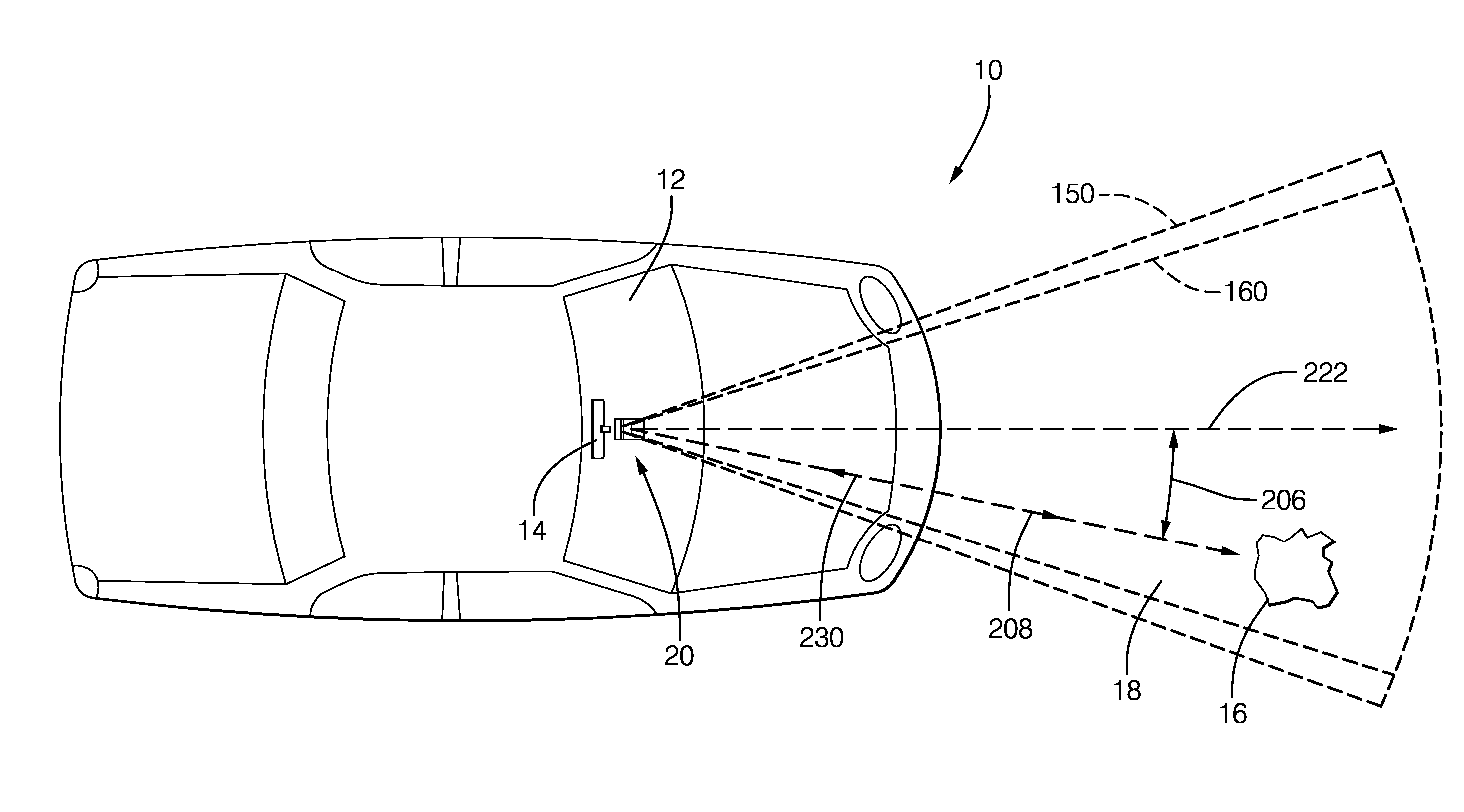
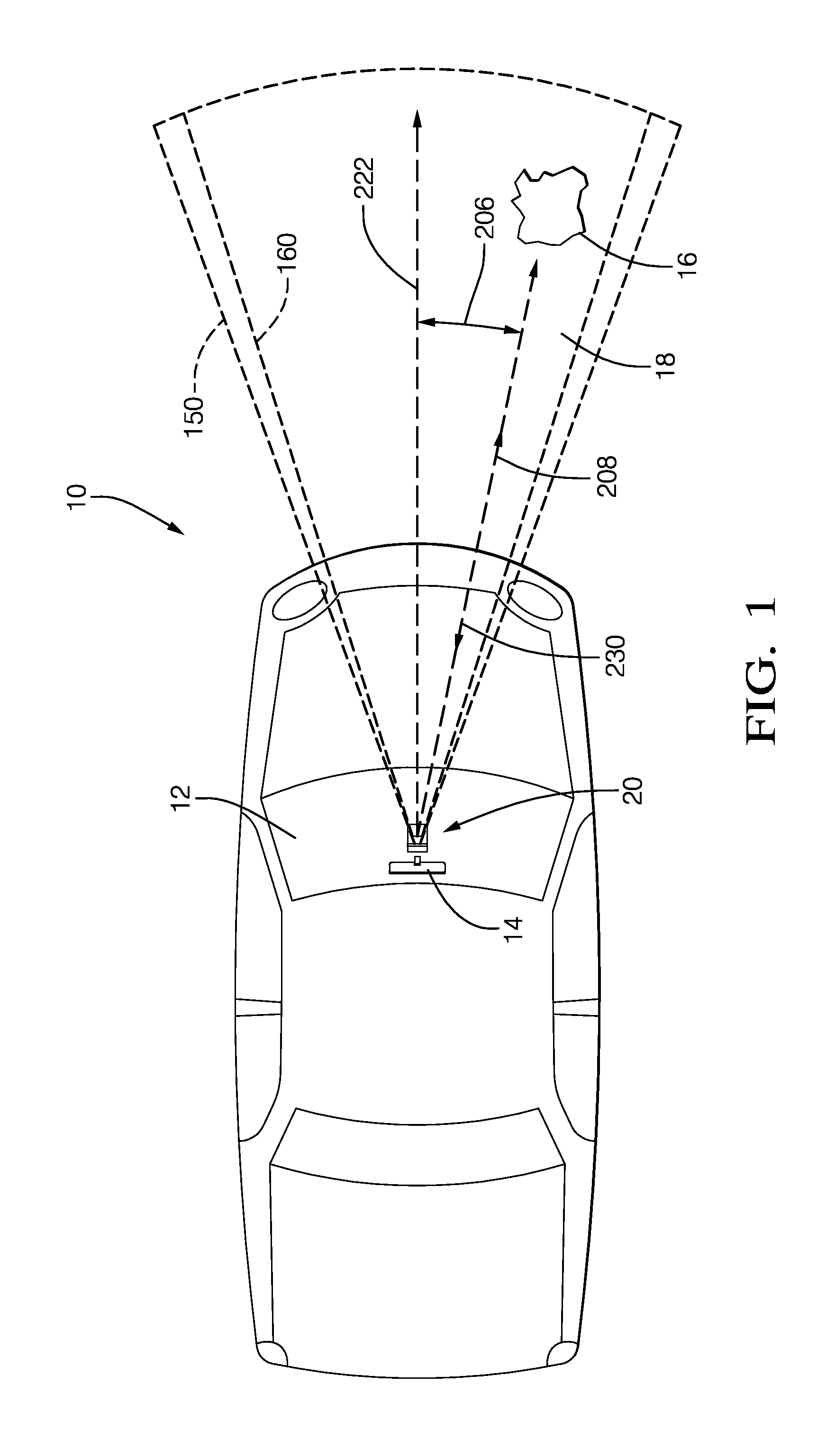
[0029]FIG. 1 illustrates a non-limiting example of a vehicle 10. The vehicle 10 is equipped with a sensor module 20, hereafter the module 20, which is generally shown located in an interior compartment of the vehicle behind a window 12 of the vehicle 10. While an automobile is illustrated, it will be evident that the module 20 may also be suitable for use on other vehicles such as heavy duty on-road vehicles like semi-tractor-trailers, and off-road vehicles such as construction equipment. In this non-limiting example, the module 20 is located behind the windshield and generally forward of a rearview mirror 14. Alternatively, the module 20 may be positioned to ‘look’ through a side or rear window of the vehicle 10.

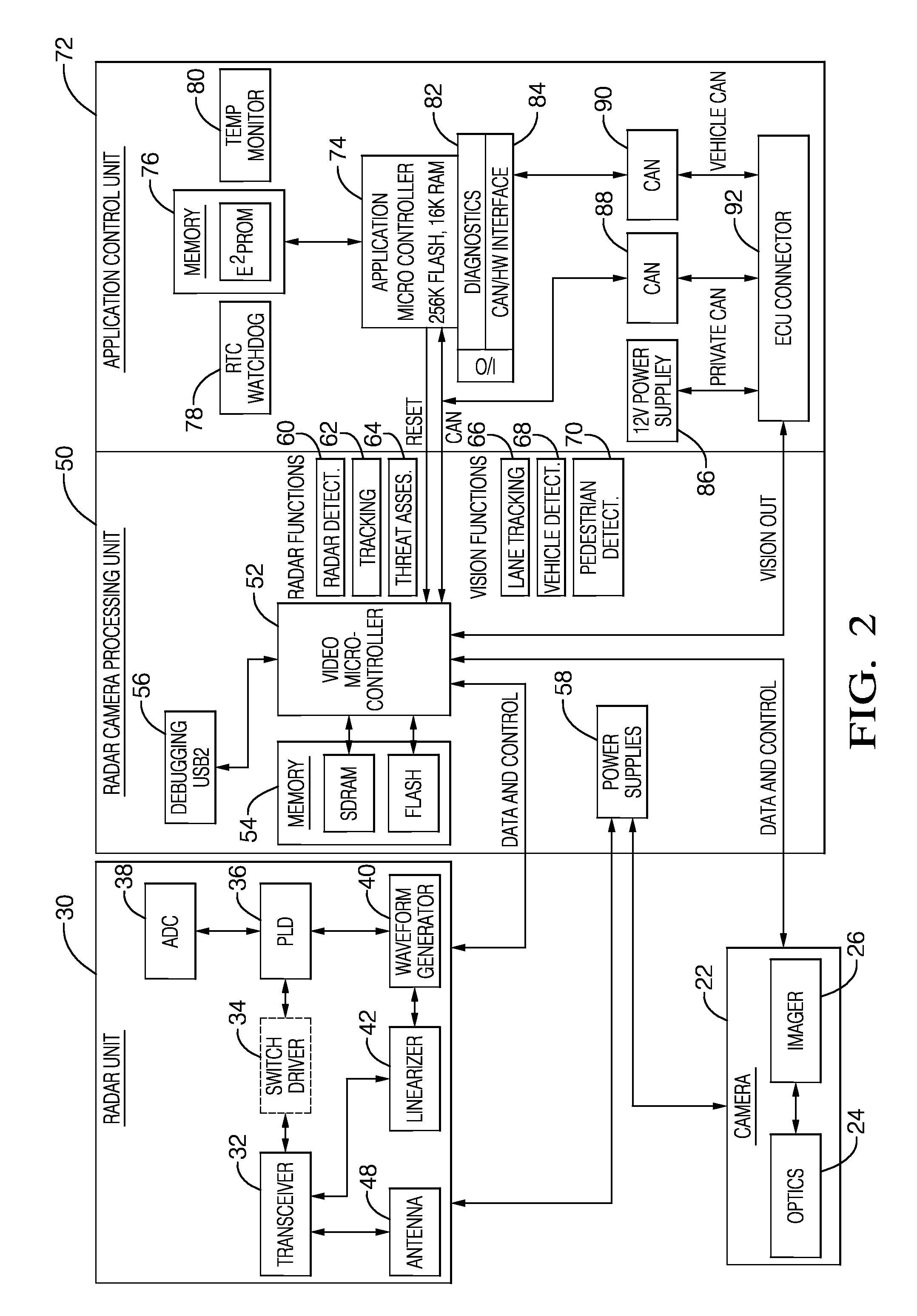
[0030]The module 20 includes a radar unit 30 (FIG. 2) for transmitting radar signals through the window 12 to detect an object 16 through the window 12 and in an area 18 about the vehicle 10. In the example, the area 18 is shown as generally forward of the vehicle 10 and in...


PUM


Abstract

A radar antenna assembly includes a microstrip patch, a hybrid coupler, a phase shifter, and a power divider. The microstrip patch is configured to emit a radar signal. The radar signal is characterized by a transmitted polarization of the radar signal. The transmitted polarization is influenced by a first transmit signal received at a first port of the microstrip patch and a second transmit signal received at a second port of the microstrip patch. The hybrid coupler is configured to orthogonally combine a first input signal and a second input signal to output the first transmit signal and the second transmit signal. The phase shifter is operable to vary the phase of the second input signal relative to the first input signal. The power divider is configured to divide unequally a source signal so the amplitudes of the first input signal and the second input signal are substantially equal.

Description

CROSS-REFERENCE TO RELATED APPLICATION[0001]This application is a continuation-in-part application and claims the benefit of U.S. patent application Ser. No. 14 / 073,489, entitled RADAR SENSOR MODULE, and filed on Nov. 6, 2013, the entire disclosure of which is hereby incorporated herein by reference.TECHNICAL FIELD OF INVENTION[0002]The present invention generally relates to radar antenna assembly, and more specifically relates to a radar antenna assembly that includes a microstrip patch, a hybrid coupler, a phase shifter, and a power divider.BACKGROUND OF INVENTION[0003]Radar and camera sensors are often employed on vehicles to enable systems for enhanced vehicle safety including Adaptive Cruise Control (ACC), Forward Collision Warning (FCW), collision mitigation, or avoidance via autonomous braking, pre-crash functions such as airbag arming or pre-activation, and Lane Departure Warning (LDW). Systems that employ both radar and camera sensors provide high level active safety capabi...

Claims


Application Information

Patent Timeline
IPC IPC(8): G01S7/282H01Q1/32H01Q9/04G01S13/931
CPCG01S7/282H01Q1/3233H01Q9/045G01S7/025G01S13/867G01S13/931H01Q1/1271H01Q1/3291H01Q9/0435H01Q15/04H01Q21/0075H01Q21/08G01S7/032G01S2013/93276
Inventor SHI, SHAWN
Owner APTIV TECH LTD
Why Eureka
Try Eureka