Low profile, antenna array for an RFID reader and method of making same

a low-profile, antenna array technology, applied in the direction of waveguide type devices, particular array feeding systems, instruments, etc., can solve the problems of increasing cost and size, limiting the likelihood of multi-path signal replicas confounding the receiver of the reader, and increasing the complexity of the array

Active Publication Date: 2015-05-07
SYMBOL TECH LLC
View PDF17 Cites 40 Cited by
  • Summary
  • Abstract
  • Description
  • Claims
  • Application Information

AI Technical Summary

Problems solved by technology

In fact, to maximize the likelihood of detecting the tag, the RFID system may benefit from the flexibility of generating multiple polarization states for each beam steering angle, thus limiting the likelihood that multi-path signal replicas confound a receiver of the reader.
This typically requires each antenna element of the array to be more complex, or the design of complex signal-routing networks, both factors being associated with an increased cost and size.
This is undesirably large for a convenient, unobtrusive, aesthetic installation, especially in an existing venue.
Although decreasing the distance between the antenna elements results in a desirably smaller array, it is typically obtained at the expense of lower port isolation and poorer gain and beam-scanning performance caused by mutual coupling.
Mutual coupling between the antenna elements typically results in wasted transmit power during transmission, and a lower received power from incoming signals during reception.
It can also limit the effective beam steering angle range.

Method used


Image

  • Low profile, antenna  array for an RFID reader and method of making same
  • Low profile, antenna  array for an RFID reader and method of making same
  • Low profile, antenna  array for an RFID reader and method of making same

Examples


Embodiment Construction

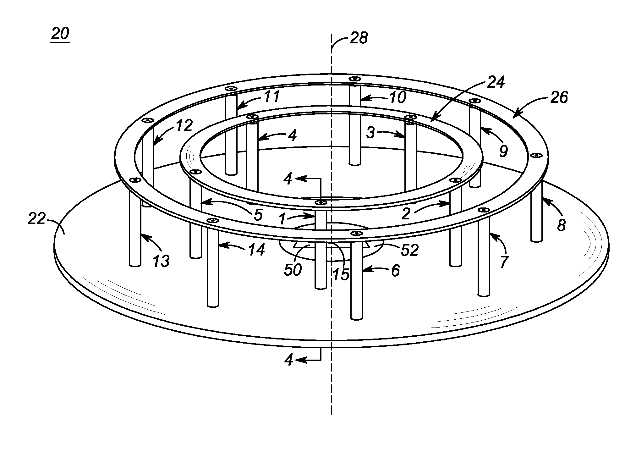
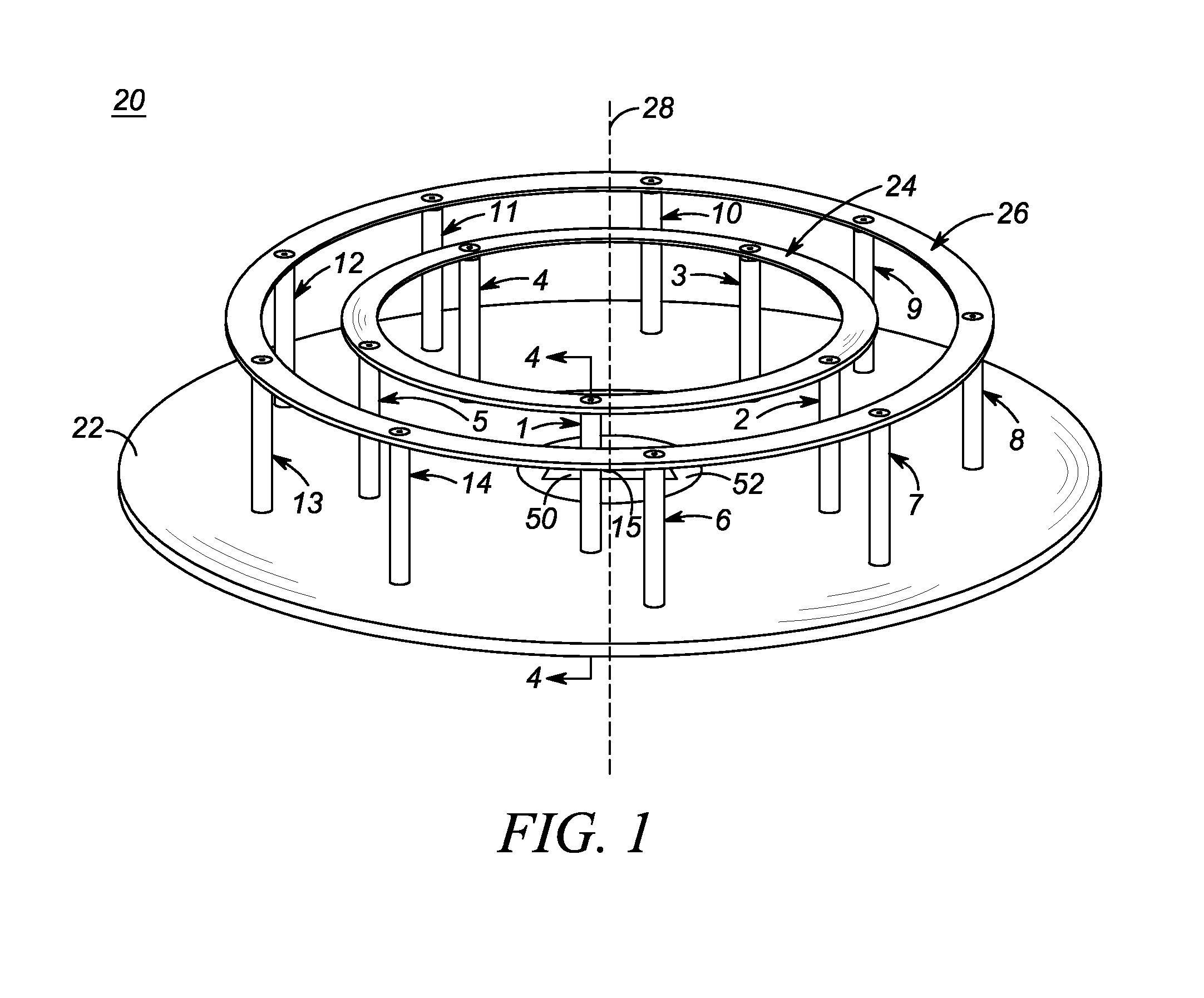
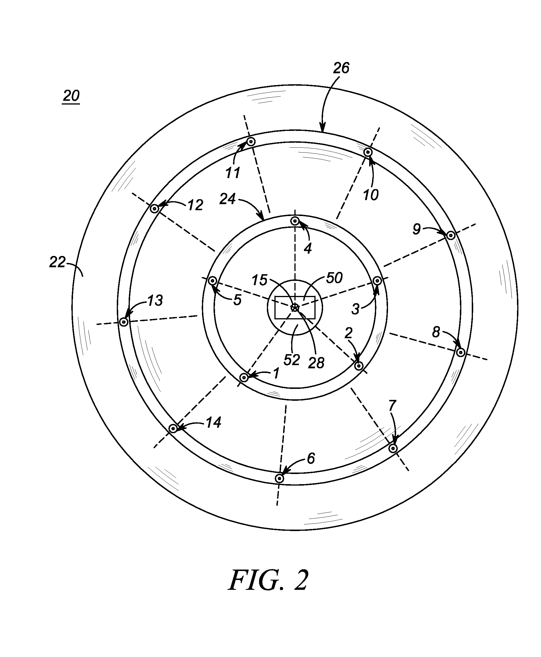
[0015]One aspect of this disclosure relates to an antenna array that includes a ground support, e.g., a ground plane; an electrically conductive, first endless element, e.g., a first circular element, mounted on, and at an elevation away from, the ground support, the first endless element extending about a central axis at a first distance transversely of the central axis along a first perimeter; and a plurality of first ports successively arranged, preferably equiangularly, apart along the first perimeter of the first endless element about the central axis for conveying radio frequency signals in a first operating band of frequencies. The first perimeter is substantially equal to an odd multiple of one-half of a guided wavelength at a center frequency of the first operating band. Each adjacent pair of first ports is successively spaced apart by a first spacing constituting a whole multiple of one-half of the guided wavelength at the center frequency of the first operating band. Each...


PUM

PropertyMeasurementUnit
frequencyaaaaaaaaaa
distanceaaaaaaaaaa
impedanceaaaaaaaaaa

Abstract

An antenna array, especially for use with a radio frequency identification reader, includes a ground plane and a pair of concentric, first and second, circular elements mounted at an elevation relative to the ground plane. First ports are arranged along the perimeter of the first element, and second ports are arranged along the perimeter of the second element. Each port conveys radio frequency signals in an operating band of frequencies. Each perimeter is substantially equal to an odd multiple of one-half of a guided wavelength at a center frequency of the respective operating band. Each adjacent pair of first ports, or adjacent pair of second ports, is successively spaced apart by a spacing constituting a whole multiple of one-half of the guided wavelength at the center frequency of the respective operating band. A polarized patch antenna may be positioned within the circular elements.

Description

CROSS REFERENCE TO RELATED APPLICATION[0001]The present disclosure is related to, and claims the priority benefit of, U.S. patent application Ser. No. 14 / 073,177, filed Nov. 6, 2013, the entire contents of which are hereby incorporated herein by reference thereto.BACKGROUND OF THE INVENTION[0002]The present disclosure relates generally to a compact, low profile, low-cost, multi-port, antenna array and to a method of making such an antenna array and, more particularly, to using such an antenna array with a radio frequency (RF) identification (RFID) reader for scanning RFID tags associated with items in a controlled area, especially for inventory control of the RFID-tagged items.[0003]RFID systems are well known and are commonly utilized for item tracking, item identification, and inventory control in manufacturing, warehouse, and retail environments. Briefly, an RFID system includes two primary components: a reader (also known as an interrogator), and a tag (also known as a transpond...

Claims


Application Information

Patent Timeline
Patent Type & Authority Applications(United States)
IPC IPC(8): H01Q21/00
CPCH01Q21/0087H01Q21/0006G06K7/10316G06K7/10346H01Q1/2216H01Q3/247H01Q9/0464H01Q19/10H01Q21/065H01Q25/005Y10T29/49016
Inventor BIT-BABIK, GIORGI G.FARAONE, ANTONIO
Owner SYMBOL TECH LLC
Why Eureka
Try Eureka