
Bone fragment tracking

a technology of bone fragments and surgical instruments, applied in the field of surgical instruments for tracking bone movement, can solve the problems that the time and cost of medical imaging may not always enable liberal use of such tools, and it is generally not practical to employ costly and time-consuming three-dimensional imaging techniques at that tim

Active Publication Date: 2015-05-07
THE JOHN HOPKINS UNIV SCHOOL OF MEDICINE
View PDF7 Cites 17 Cited by
  • Summary
  • Abstract
  • Description
  • Claims
  • Application Information

AI Technical Summary

Benefits of technology

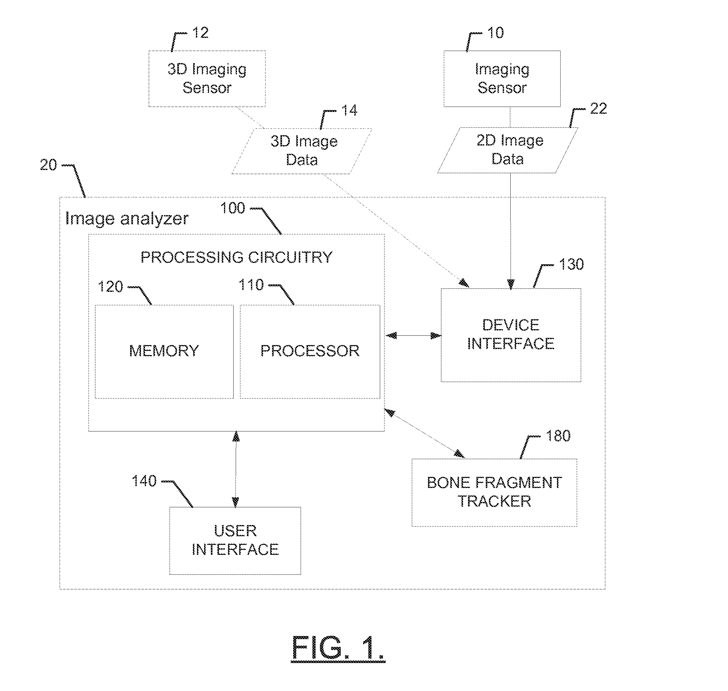
This patent describes a system and method for using medical imaging techniques to help position and track a bone fragment during surgery. The system includes a 2D imaging system and a 3D imaging system, which can obtain a 3D model of the area where the bone fragment is located before surgery. Fiducial markers are inserted into the area and the 2D image is back projected to the 3D model. During surgery, the bone fragment may be moved and the position of the markers can be extracted. The movement of the bone fragment can then be calculated based on the marker positions. This system can provide a more accurate and efficient way to navigate and position bones during surgery.

Problems solved by technology

Although medical imaging techniques continue to improve, it should be appreciated that the timing and cost associated with employing medical imaging may not always enable such tools to be employed liberally at every possible point at which they might be useful.
For example, when positioning a bone fragment during surgery, although it might be desirable to track the movement of the bone fragment in three dimensional space during the surgical procedure, it is generally not practical to employ costly and time consuming three dimensional imaging techniques at that time.

Method used


Image

  • Bone fragment tracking
  • Bone fragment tracking
  • Bone fragment tracking

Examples


Embodiment Construction

[0002]This invention was made with government support under contract number R01EB006839 awarded by the National Institutes of Health (NIH). The government has certain rights in the invention.

TECHNICAL FIELD

[0003]Exemplary embodiments of the present disclosure generally relate to a surgical system for tracking bone movement, and more specifically relate to employment of image analysis to facilitate tracking of bone fragment movement during or after surgery.

BACKGROUND

[0004]Modern medicine benefits greatly from the vast number of technical advancements that are at the disposal of practitioners. Among the key technical advancements that facilitate improved medical care, medical imaging devices have been extremely important to enabling practitioners to identify issues, address those issues and verify proper healing. Computed tomography (CT) scans, x-rays, magnetic resonance imaging (MRI), ultrasound images, and the like have all been employed to great effect in improving medical care.

[00...


PUM


Abstract

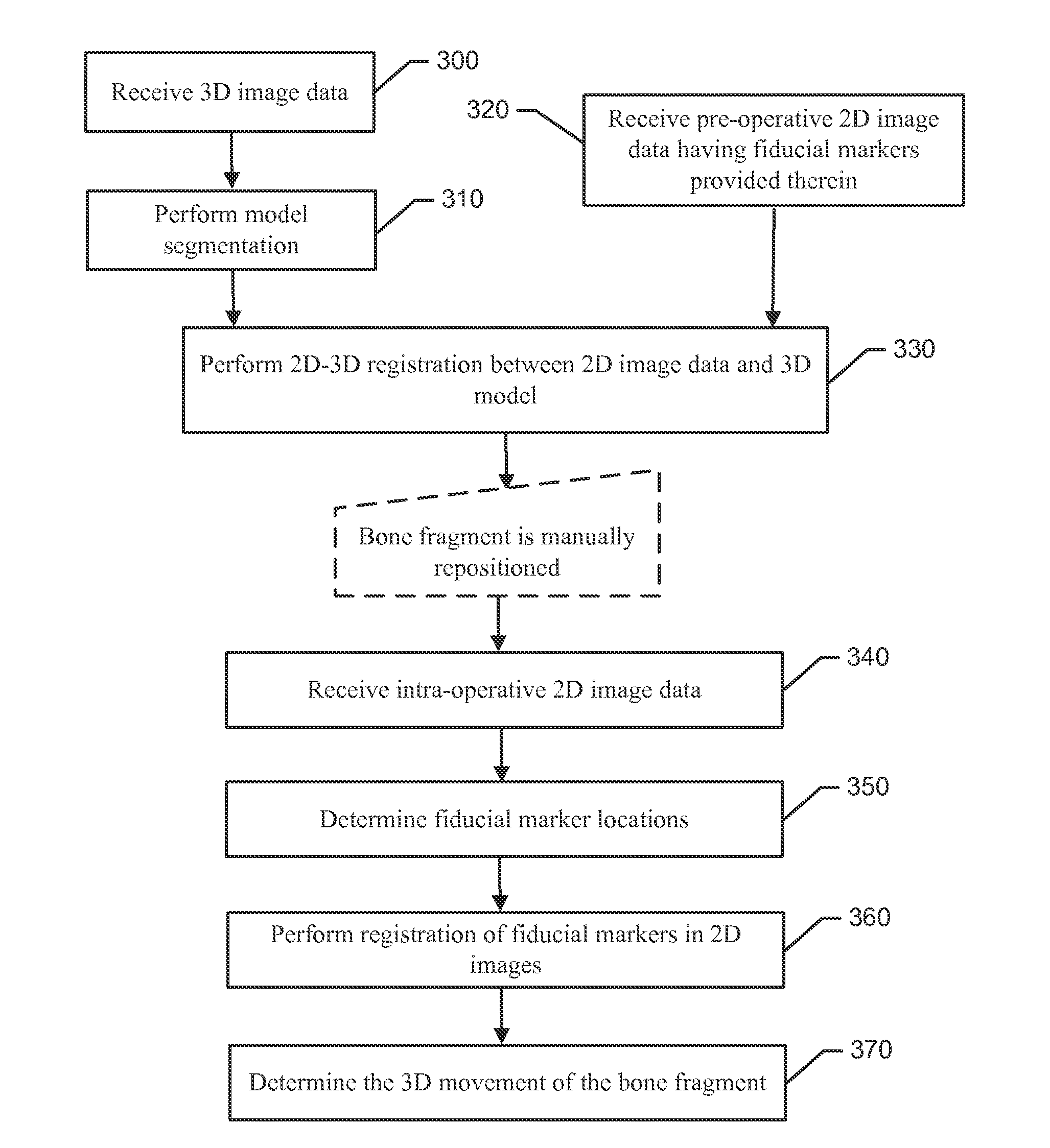
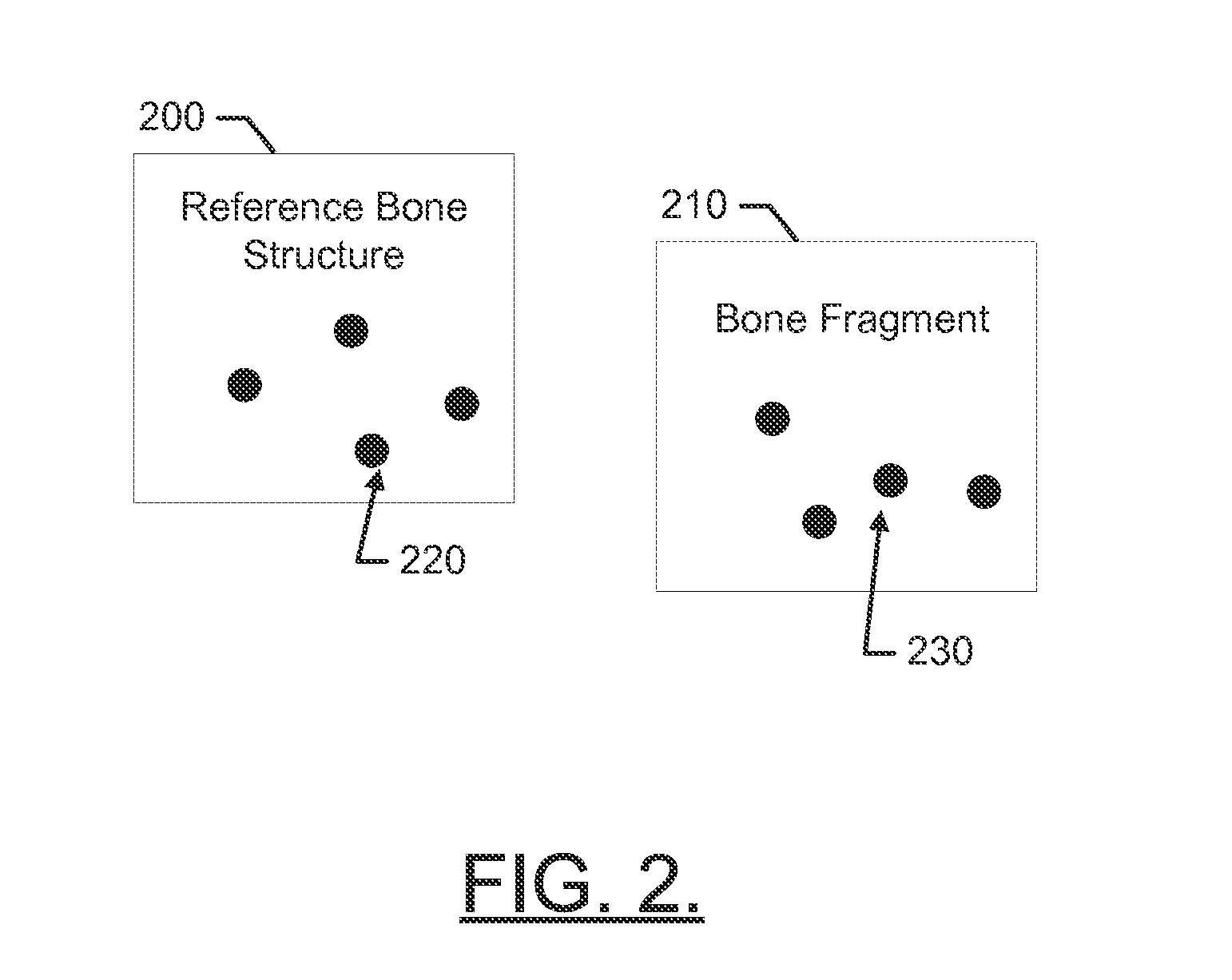
A method of determining bone fragment navigation may include receiving pre-operative 2D image data of a reference bone structure and a bone fragment. The reference bone structure may include a first set of fiducial markers provided thereon, and the bone fragment may include a second set of fiducial markers provided thereon. The method may further include performing a 2D-3D registration between the pre-operative 2D image data and a 3D model of the reference bone structure and the bone fragment, after manual repositioning of the bone fragment, receiving second 2D image data, performing 2D-2D registration of the first set of fiducial markers and the second set of fiducial markers between the pre-operative 2D image data and the second 2D image data, and determining 3D movement of the bone fragment based at least in part on the 2D-2D registration.

Description

CROSS-REFERENCE TO RELATED APPLICATIONS[0001]This application claims priority to and the benefit of co-pending U.S. Provisional Application Ser. No. 61 / 901,068, filed on Nov. 7, 2013, the entire contents of which are hereby incorporated herein by reference.STATEMENT OF GOVERNMENTAL INTEREST[0002]This invention was made with government support under contract number R01EB006839 awarded by the National Institutes of Health (NIH). The government has certain rights in the invention.TECHNICAL FIELD[0003]Exemplary embodiments of the present disclosure generally relate to a surgical system for tracking bone movement, and more specifically relate to employment of image analysis to facilitate tracking of bone fragment movement during or after surgery.BACKGROUND[0004]Modern medicine benefits greatly from the vast number of technical advancements that are at the disposal of practitioners. Among the key technical advancements that facilitate improved medical care, medical imaging devices have be...

Claims


Application Information

Patent Timeline
Patent Type & Authority Applications(United States)
IPC IPC(8): G06T7/20G06T3/00G06T7/00
CPCG06T7/20G06T2207/30008G06T3/0068G06T7/0012G06T7/251G06T2207/10081G06T2207/10088G06T2207/10116G06T2207/20076G06T2207/30204
Inventor MURPHY, RYAN J.ARMAND, MEHRANARMIGER, ROBERT S.OTAKE, YOSHITOLEPISTO, JYRI
Owner THE JOHN HOPKINS UNIV SCHOOL OF MEDICINE
Learn More