
Three-Level Power Converter

Active Publication Date: 2015-05-07
SEMIKRON ELECTRONICS GMBH & CO KG
View PDF2 Cites 4 Cited by
  • Summary
  • Abstract
  • Description
  • Claims
  • Application Information

AI Technical Summary

Benefits of technology

The invention provides an improved device for converting power at three levels, which can be easily connected to other devices with low inductance. This allows for the efficient transfer of power between devices.

Problems solved by technology

The configuration of the electrical terminals of technically conventional 3-level power converter devices, by means of which technically conventional 3-level power converter devices are electrically connected with one another so as to implement a 3-level power converter, has the disadvantage that during commutation processes the latter has a relatively high effective parasitic inductance, which in the case of commutation processes has as a consequence high switching surges that reduce the switching speed and switching frequency that can be implemented on the power semiconductor switches of the 3-level power converter devices.

Method used


Image

  • Three-Level Power Converter
  • Three-Level Power Converter
  • Three-Level Power Converter

Examples


Embodiment Construction

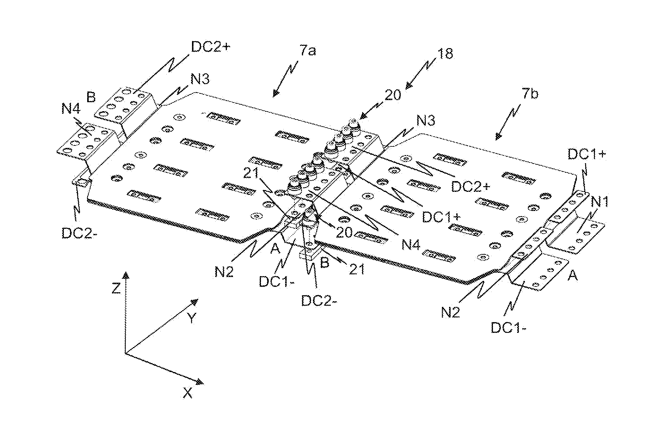
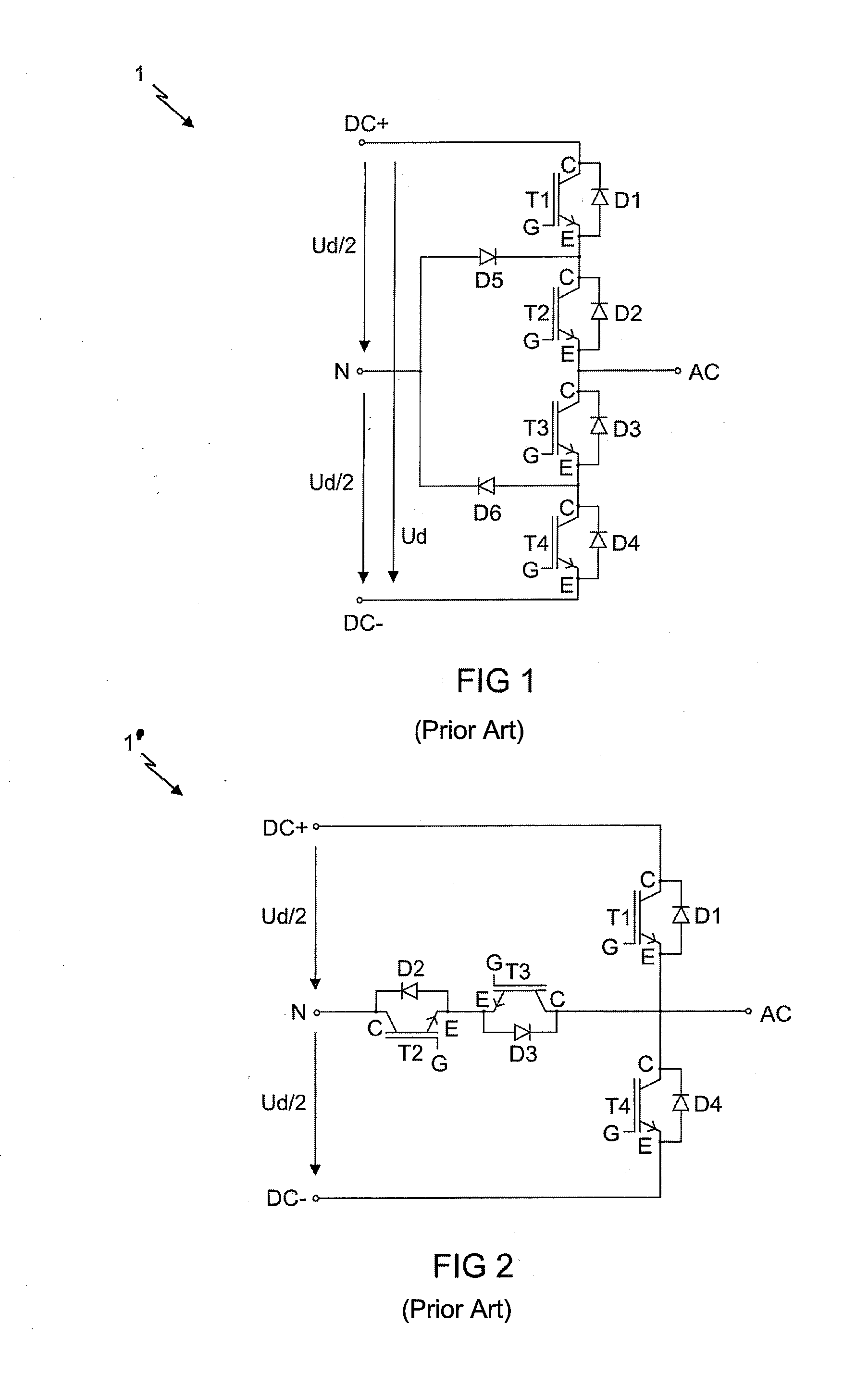
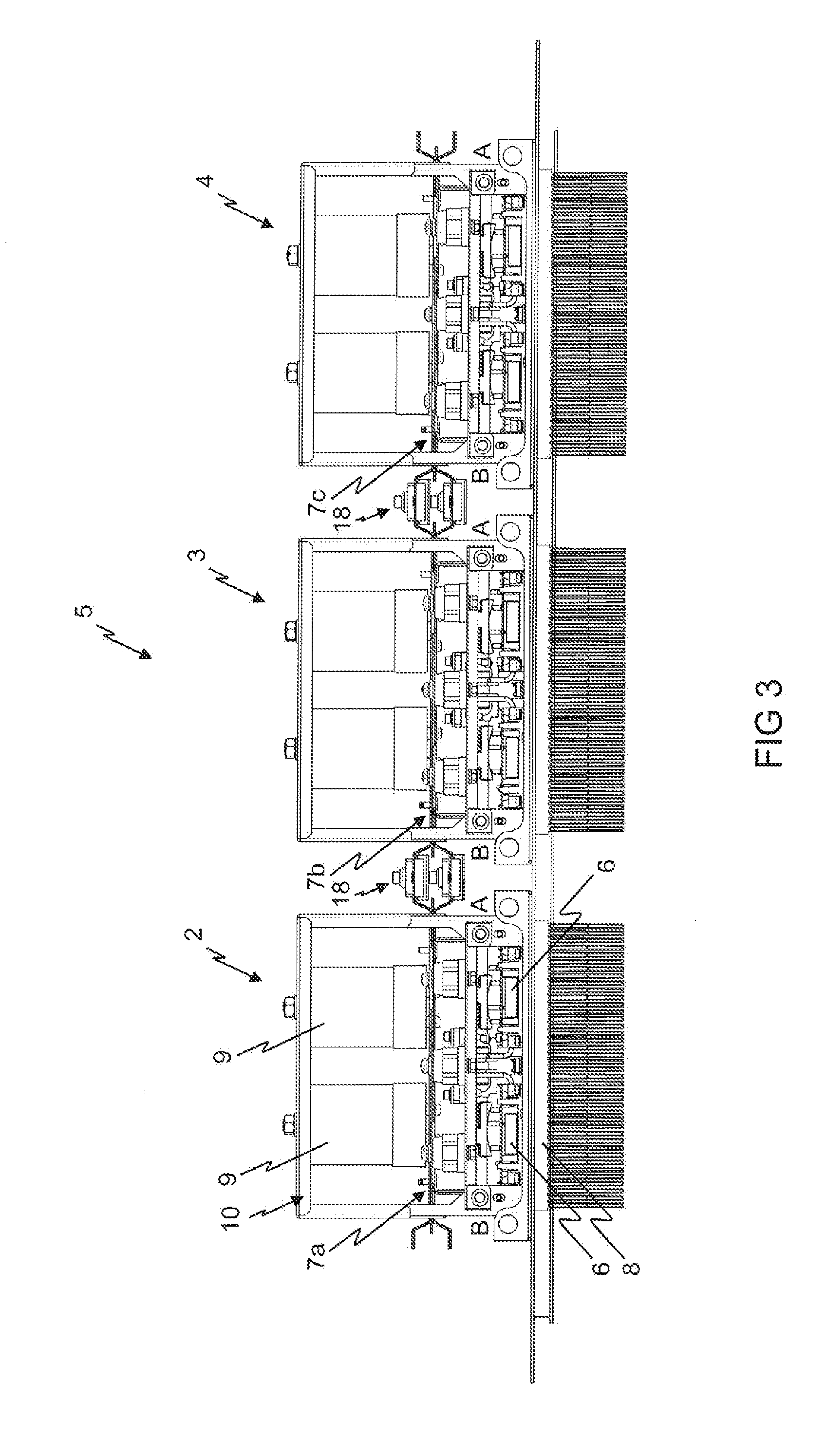
[0046]FIG. 1 shows an example of an electrical circuit diagram of a prior art 3-level half-bridge power converter 1. Three-level half-bridge power converter 1 has a first power semiconductor switch T1, a second power semiconductor switch T2, a third power semiconductor switch T3, a fourth power semiconductor switch T4, a first diode D1, a second diode D2, a third diode D3, a fourth diode D4, a fifth diode D5, and a sixth diode D6. These components are electrically connected, as represented in FIG. 1, so as to form 3-level half-bridge power converter 1. Three-level half-bridge power converter 1 is fed from two voltage sources that are not represented in FIG. 1; each generates half the intermediate circuit voltage Ud / 2, so that the intermediate circuit voltage Ud is applied between the direct voltage positive potential terminal DC+ and the direct voltage negative potential terminal DC−, and the direct voltage positive potential terminal DC+ has the positive intermediate circuit half-v...


PUM


Abstract

A 3-level power converter device with power semiconductor components including a first direct voltage positive potential terminal, a first direct voltage negative potential terminal, and first and second neutral voltage potential terminals. The first and second neutral voltage potential terminals are electrically conductively connected. The first direct voltage positive potential terminal and the first neutral voltage potential terminal form a first terminal pair, and the second neutral voltage potential terminal and the first direct voltage negative potential terminal form a second terminal pair. The first and second terminal pairs are arranged one behind another in a second direction. The first direct voltage positive potential terminal and the first neutral voltage potential terminal are arranged one above another in a third direction, and the second neutral voltage potential terminal and the first direct voltage negative potential terminal are arranged one above another in the third direction.

Description

CROSS-REFERENCE TO RELATED APPLICATION[0001]This application is a non-provisional application which claims domestic priority from prior-filed provisional application Ser. No. 61 / 833,359, filed Jun. 10, 2013.BACKGROUND OF THE INVENTION[0002]1. Field of the Invention[0003]The invention relates to a 3-level power converter.[0004]2. Description of the Related Art[0005]A 3-level power converter can be distinguished from the widely used conventional power converters by the fact that, when it is operated as an alternating current converter, on its load terminal AC on the alternating voltage side it can not only generate an electrical alternating voltage in the same way as a conventional power converter, the value of which essentially corresponds to the electrical positive or negative electrical voltage of the intermediate circuit voltage Ud, but in addition can generate an electrical voltage on the load terminal AC on the alternating voltage side, the value of which corresponds essentially...

Claims


Application Information

Patent Timeline
IPC IPC(8): H01R13/652
CPCH01R13/652H05K7/14324H05K7/14329H05K7/023H05K7/1432
Inventor YAMKOVOY, TATIANA
Owner SEMIKRON ELECTRONICS GMBH & CO KG
Learn More