
Medical Connector Having Locking Engagement

a technology of medical connectors and locking engagements, which is applied in the direction of hose connections, packaging foodstuffs, packaged goods, etc., can solve the problems of medical and pharmacological staff being exposed to drugs or solvents, particularly serious problems, and staff being exposed to medical fluids through contamination

Active Publication Date: 2015-05-07
BECTON DICKINSON & CO
View PDF23 Cites 62 Cited by
  • Summary
  • Abstract
  • Description
  • Claims
  • Application Information

AI Technical Summary

Benefits of technology

The patent describes a medical connector system that allows two connectors to be locked together. The connectors have projections and grooves that fit together to create a secure lock. The system also includes a biasing member that helps to lock the connectors together. The technical effect of this system is to provide a reliable and secure way to connect medical devices together, allowing for easy disconnection when needed.

Problems solved by technology

A problem in connection with drug preparation, drug administration, and other similar handling is the risk that medical and pharmacological staff are exposed to drugs or solvents which might escape into the ambient air.
This problem is particularly serious when cytotoxins, antiviral drugs, antibiotics, and radiopharmaceuticals are concerned.
In each of these steps, staff may be exposed to the medical fluid by means of contamination.
The contaminations may contaminate the staff through their lungs or vaporized medical fluid or aerosol in the air which condensates on the skin to thereafter penetrate the skin of the staff.
Some medicaments are even known to penetrate protection gloves and thereby contaminate the staff.
Exposure to contaminations like this may, on a long term basis, give rise to alarmingly high concentrations of medicaments in the blood or the human body of the staff described above.
It has been understood that due to the many transferring steps between e.g. vials, syringes, infusion systems etc., the risk for contamination during the actual insertion and retraction of a needle from the container, e.g. a vial, needs to be contained.

Method used


Image

  • Medical Connector Having Locking Engagement
  • Medical Connector Having Locking Engagement
  • Medical Connector Having Locking Engagement

Examples


Embodiment Construction

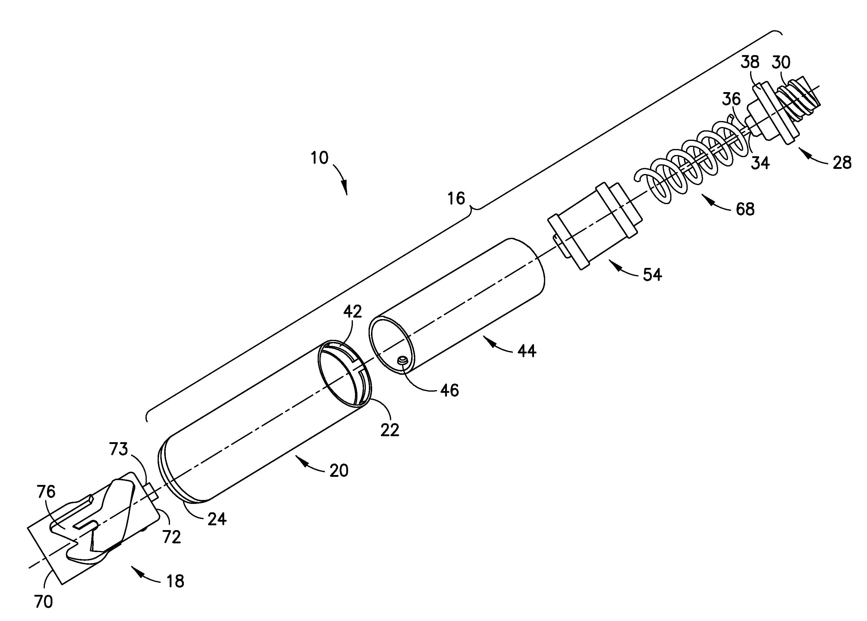
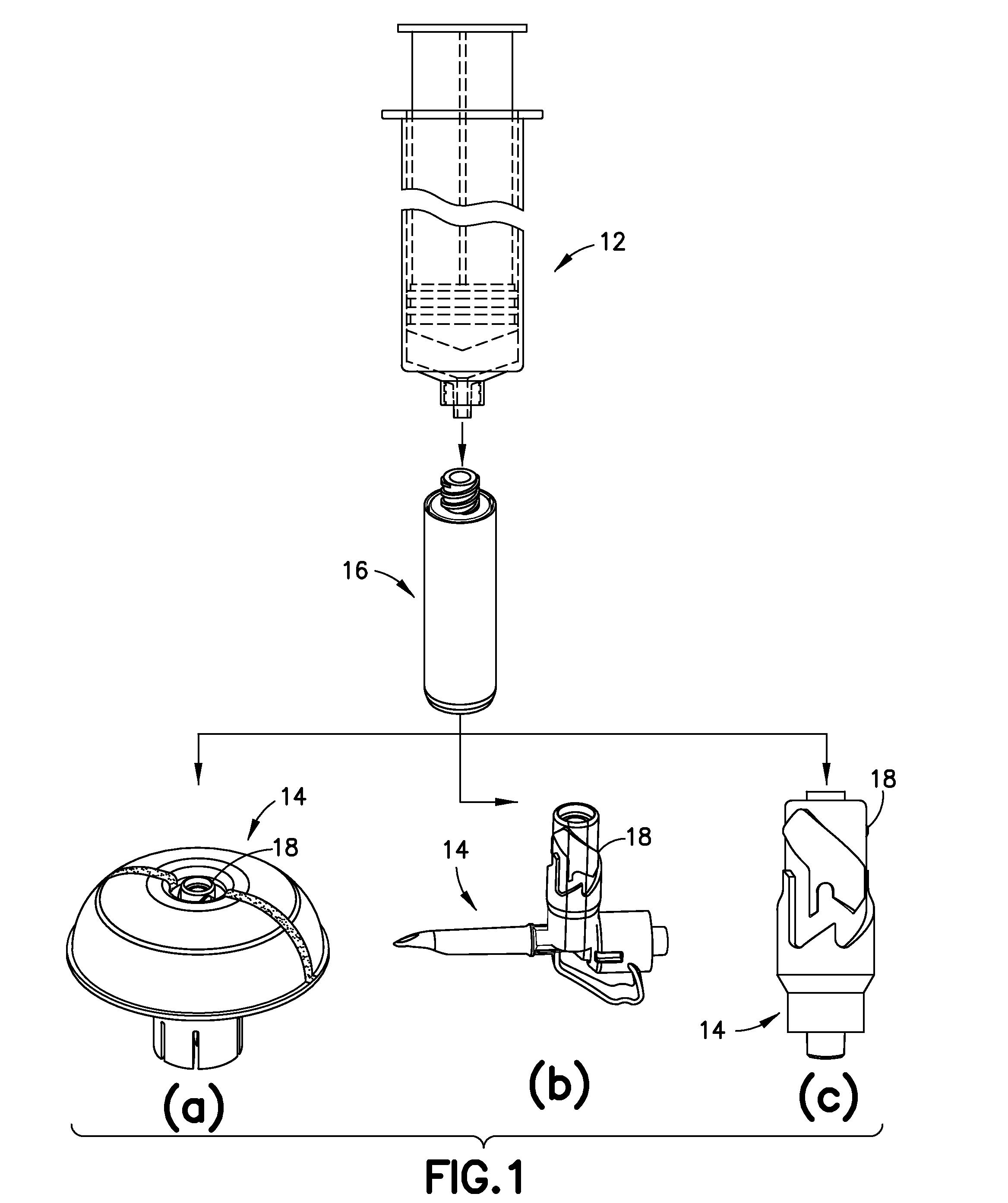
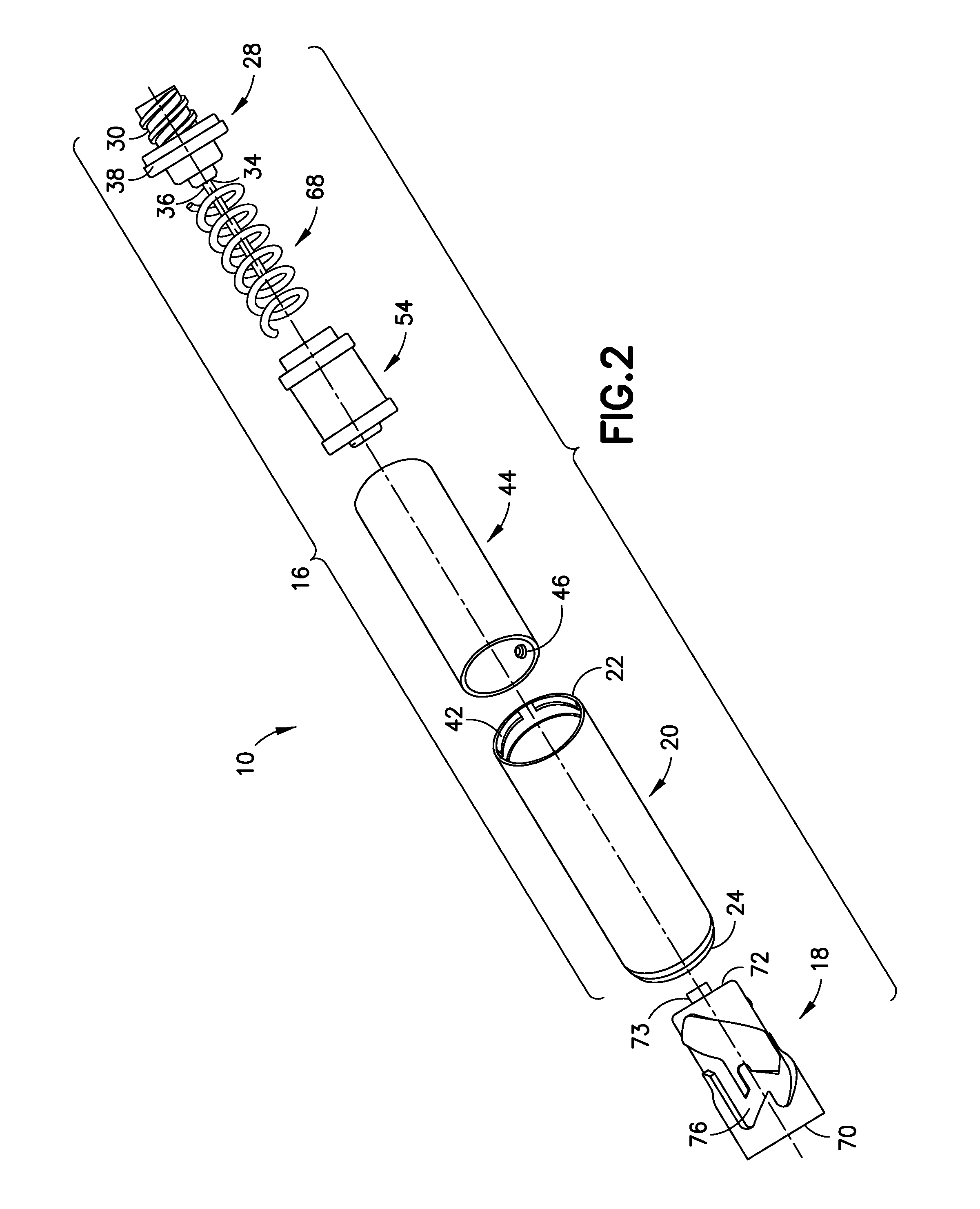
[0082]For purposes of the description hereinafter, the terms such as “end”, “upper”, “lower”, “right”, “left”, “vertical”, “horizontal”, “top”, “bottom”, “lateral”, “longitudinal” and derivatives thereof shall relate to the invention as it is oriented in the drawing figures. However, it is to be understood that the invention may assume various alternative variations and step sequences, except where expressly specified to the contrary. It is also to be understood that the specific devices and processes illustrated in the attached drawings, and described in the following specification, are simply exemplary aspects of the invention. Hence, specific dimensions and other physical characteristics related to the aspects disclosed herein are not to be considered as limiting. Further, it is to be understood that the invention may assume various alternative variations and step sequences, except where expressly specified to the contrary.

[0083]The present invention is directed to a connector sy...


PUM


Abstract

A medical connector system including a first connector and a second connector. The first connector has a housing, a biasing member, and at least one projection. The second connector has at least one groove for receiving the at least one projection. The proximal end of the second connector is configured to be at least partially disposed within the distal end of the housing of the first connector. Upon application and release of a first set of opposing axial forces applied to the connector system, the first connector is locked to the second connector and, upon application and release of a second set of opposing axial forces, the first connector is released from the second connector. The connectors may include indicators to show when the connector system is in the locked position.

Description

CROSS-REFERENCE TO RELATED APPLICATION[0001]This application claims priority to U.S. Provisional Application Ser. No. 61 / 900,647, filed Nov. 6, 2013, which is hereby incorporated by reference in its entirety.BACKGROUND OF THE INVENTION[0002]1. Field of the Invention[0003]The present invention relates to a connector system for a medical device. More specifically, the present invention relates to a connector system for enabling fluid transfer between a first medical device for receiving and / or dispensing fluids and a second medical device for receiving and / or dispensing fluids.[0004]2. Description of Related Art[0005]A problem in connection with drug preparation, drug administration, and other similar handling is the risk that medical and pharmacological staff are exposed to drugs or solvents which might escape into the ambient air. This problem is particularly serious when cytotoxins, antiviral drugs, antibiotics, and radiopharmaceuticals are concerned. Other hazardous areas may be s...

Claims


Application Information

Patent Timeline
Patent Type & Authority Applications(United States)
IPC IPC(8): A61J1/20A61J1/18
CPCA61J1/2096A61J2001/2048A61J1/18A61M39/1011A61M2039/1016A61M2039/1033A61J1/201A61J1/2065A61J2205/40A61J2205/50A61M39/10A61M39/14A61M2039/1066A61M2039/1072
Inventor SANDERS, LAURIECANCELLIERI, JUDEYEVMENENKO, YAN
Owner BECTON DICKINSON & CO
Features
  • Generate Ideas
  • Intellectual Property
  • Life Sciences
  • Materials
  • Tech Scout
  • Unparalleled Data Quality
  • Higher Quality Content
  • 60% Fewer Hallucinations
Learn More