Robot, robot system, and robot control device

a robot and control device technology, applied in the field of robots, can solve the problems of inability to accurately perform the control of keeping the polishing force (the force applied to the target) fixed, the accuracy of force detection deteriorates, and the cycle time of the work performed using the force sensor increases, so as to achieve the effect of accurately keeping the force applied to the machining target fixed and accurate keeping the force applied to the machining targ

Active Publication Date: 2015-05-07
SEIKO EPSON CORP
View PDF4 Cites 34 Cited by
  • Summary
  • Abstract
  • Description
  • Claims
  • Application Information

AI Technical Summary

Benefits of technology

[0036]With this configuration, in the robot, the force sensor is provided in the robot itself rather than on the machining tool side. Consequently, the control device keeps a contact state of the machining target and the machining tool according to an output value of the force sensor on which noise is not superimposed. Therefore, it is possible to provide the control device that can accurately keep a force applied to the machining target fixed.
[0037]According to the aspects explained above, the force sensor is provided in the robot itself rather than on the machining tool side. Therefore, the robot keeps a contact state of the machining target and the machining tool according to an output value of the force sensor on which noise is not superimposed. Consequently, it is possible to provide the robot, the robot system, and the control device that can accurately keep a force applied to the machining target fixed.

Problems solved by technology

In the force sensor, accuracy of force detection is deteriorated because of a temperature change, an output drift due to a leak current of a circuit, and the like.
Consequently, a cycle time increases in the work performed using the force sensor.
Therefore, the control for keeping the polishing force (the force applied to the target) fixed cannot be accurately performed.

Method used


Image

  • Robot, robot system, and robot control device
  • Robot, robot system, and robot control device
  • Robot, robot system, and robot control device

Examples


first embodiment

Robot

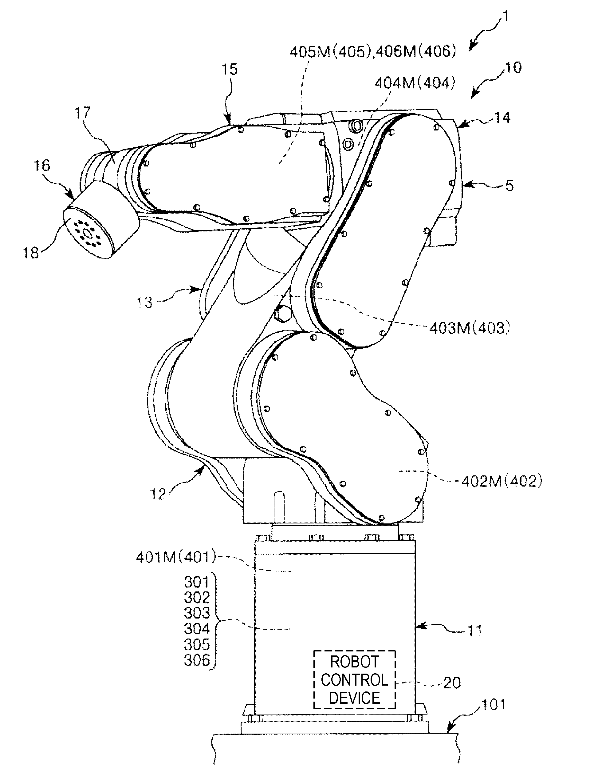
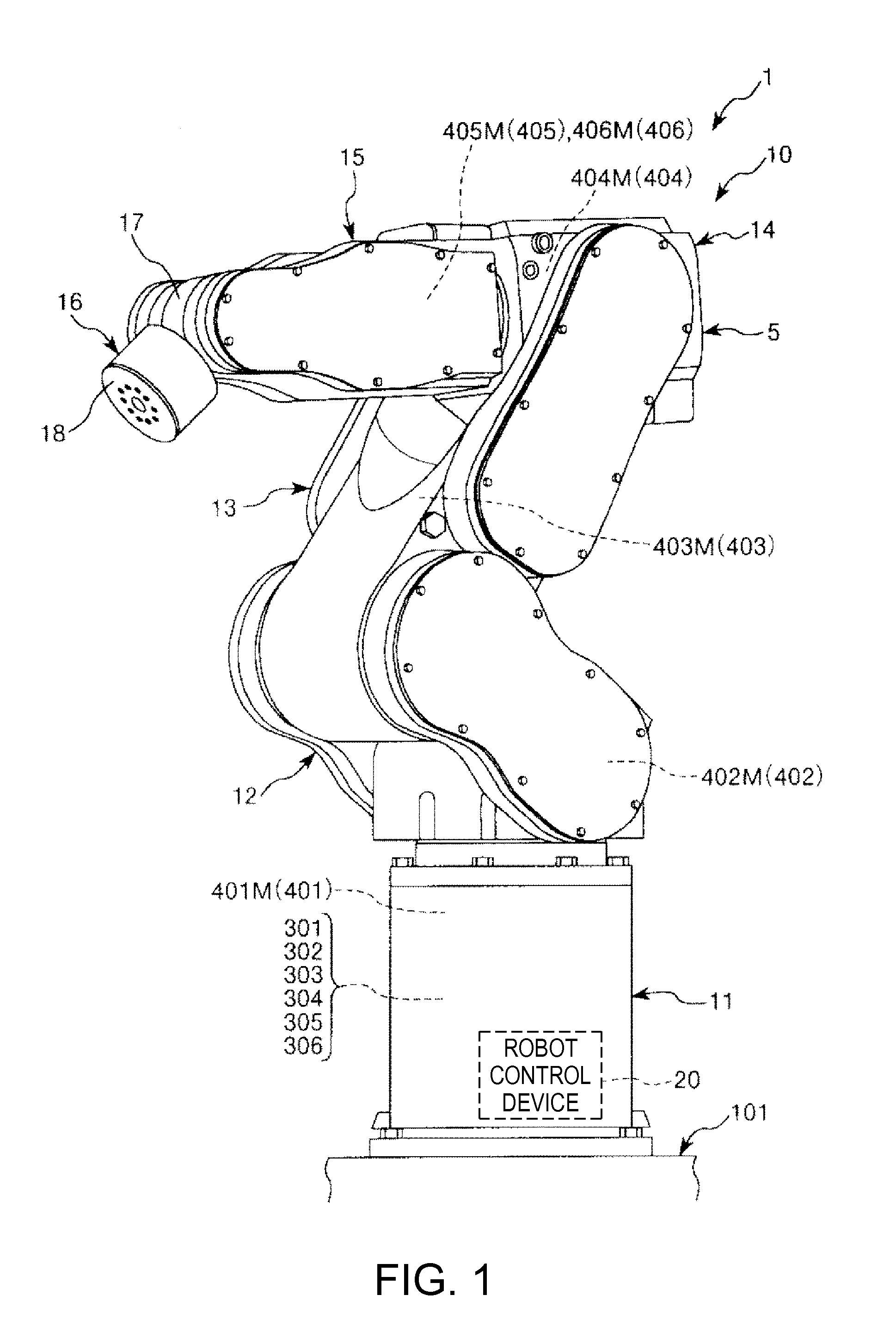
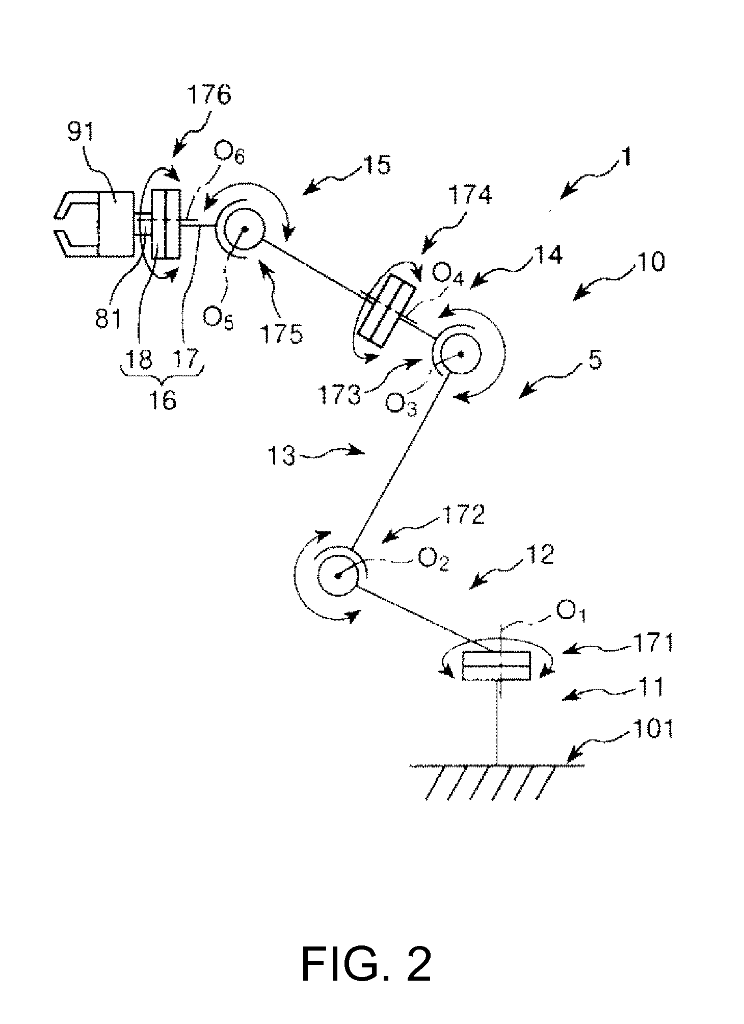
[0057]FIG. 1 is a perspective view of a robot according to a first embodiment of the invention viewed from the front side. FIG. 2 is a schematic diagram of the robot shown in FIG. 1. FIG. 3 is a block diagram of a main part of the robot shown in FIG. 1. FIG. 4 is a circuit diagram showing the configuration of a part of a force sensor of the robot shown in FIG. 1. FIG. 5 is a timing chart showing the operation of the robot shown in FIG. 1 in a period including a period of initialization of a force sensor. FIG. 6 is a flowchart for explaining a control operation of a robot control device of the robot shown in FIG. 1. FIGS. 7 to 10 are diagrams for explaining an operation in work of the robot shown in FIG. 1.

[0058]Note that, in the following explanation, for convenience of explanation, the upper side in FIGS. 1, 2, and 7 to 10 is referred to as “up” or “upward” and the lower side in the figures is referred to as “down” or “downward”. The base side in FIGS. 1, 2, and 7 to 10 is ref...

second embodiment

A Robot

[0103]FIG. 11 is a schematic diagram showing a robot according to a second embodiment of the invention.

[0104]Differences of the second embodiment from the first embodiment are mainly explained below. Explanation of similarities is omitted.

[0105]As shown in FIG. 11, a robot 1A in the second embodiment is a double-arm robot. The robot main body 10 of the robot 1A includes two robot arms 5 and a body section 110 functioning as a base (a supporting section) that supports the robot arms 5. For example, the robot 1A can perform work by gripping the insertion object 41 with one of two hands 91 and gripping the insertion target 46 with the other.

[0106]With the robot 1A, effects same as the effects in the first embodiment can be obtained.

[0107]Since the robot 1A is a double-arm robot, the robot 1A can perform various operations and can perform various kinds of work.

[0108]Note that the number of robot arms is not limited to two and may be three or more.

third embodiment

A Robot System

[0109]FIG. 12 is a perspective view showing a robot system according to a third embodiment of the invention.

[0110]Differences of the third embodiment from the first embodiment are mainly explained below. Explanation of similarities is omitted.

[0111]As shown in FIG. 12, a robot system 100 includes a robot 1B and a robot control device (a control unit) 20, which is separate from the robot 1B. In the robot 1B, the robot control device 20 is excluded from the robot 1 in the first embodiment. The robot 1B and the robot control device 20 are electrically connected by a cable 25.

[0112]Note that the robot 1B and the robot control device 20 may be configured to perform communication by radio.

[0113]With the robot system 100, effects same as the effects in the first embodiment can be obtained. Note that this embodiment can be applied to the second embodiment as well.

[0114]The robot, the robot system, and the robot control device according to the embodiments of the invention are e...


PUM


Abstract

A robot includes a robot arm, a force sensor, and a control unit configured to control the operation of the robot art. The control unit initializes the force sensor while the robot arm is moving at uniform speed. It is preferable that the control unit initializes the force sensor while the robot arm is moving at the uniform speed and the amplitude of a detection value of the force sensor is smaller than a threshold.

Description

BACKGROUND[0001]1. Technical Field[0002]The present invention relates to a robot, a robot system, and a robot control device.[0003]2. Related Art[0004]A robot including a robot arm has been known. A plurality of arm members are coupled via joint sections in the robot arm. For example, a hand is attached to the arm member on the most distal end side as an end effector. The joint sections are driven by motors. The arm members turn according to the driving of the joint sections. The robot performs work for, for example, gripping a target with the hand, moving the target to a predetermined place, and inserting the target into an opening.[0005]A force sensor is provided between the arm member on the most distal end side and the hand. In performing the work, the robot detects a force and a moment with the force sensor and performs impedance control (force control) on the basis of a detection result of the force sensor.[0006]In the force sensor, accuracy of force detection is deteriorated ...

Claims


Application Information

Patent Timeline
Patent Type & Authority Applications(United States)
IPC IPC(8): B25J9/16
CPCB25J9/1694Y10S901/02Y10S901/46Y10S901/41Y10S901/31G05B19/401B25J9/1692B25J13/085G05B2219/39058G05B2219/39529G05B2219/40599G05B2219/45058G05B2219/45064
Inventor SHIMODAIRA, YASUHIRO
Owner SEIKO EPSON CORP
Why Eureka
Try Eureka