
Power Tool and Transmission Thereof

a technology of transmission and power tools, applied in the field of transmission, can solve the problems of low strength of the needle bearing itself, the configuration cannot be used in a reverse operation power tool, and the lager size, etc., and achieve the effect of compact and/or durable structur

Inactive Publication Date: 2015-05-14
BOSCH POWER TOOLS CHINA +1
View PDF32 Cites 9 Cited by
  • Summary
  • Abstract
  • Description
  • Claims
  • Application Information

AI Technical Summary

Benefits of technology

The patent is about an improved power tool that is compact and durable. The gear transmission mechanism is designed to be arranged in a compact way by accommodating the proximal bearing in the first proximal intermediate gear. The bearing is of a type that can withstand both axial force and radial force, which increases the supporting ability of the bearings on the intermediate shaft and makes the power tool more durable overall. Additionally, by forming the receptacle portion in the first proximal intermediate gear, the weight of the mechanism is reduced and energy loss can be minimized.

Problems solved by technology

However, more stages of the gear transmission mechanism result in a lager size of it.
For example, such a configuration cannot be used in a reversely operable power tool (a tool having a tool bit that is rotatable in both forward and reverse directions).
Further, the strength of the needle bearing itself is low.
In addition, high vibration and noise are likely to be generated because the needle bearing has a large radial fitting clearance.
These factors will negatively affect cutting precision, operation comfortability and life time of the power tool.

Method used


Image

  • Power Tool and Transmission Thereof
  • Power Tool and Transmission Thereof
  • Power Tool and Transmission Thereof

Examples


Embodiment Construction

[0019]Now some illustrative preferred embodiments of the disclosure will be described with reference to the drawings.

[0020]The disclosure relates to power tools, in particular portable power tools, such as saws, drills, grinding tools and the like, which may comprise various gear transmission mechanisms. A circular saw is used here as an example for describing the principle of the disclosure though, the disclosure is also applicable in other types of power tools.

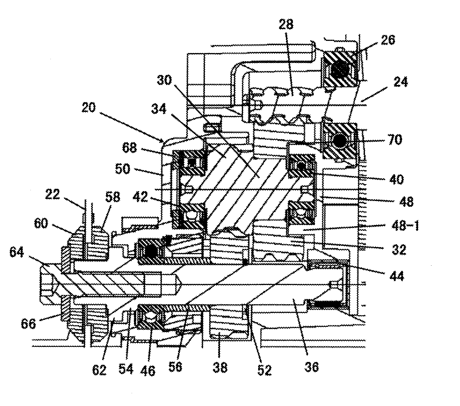
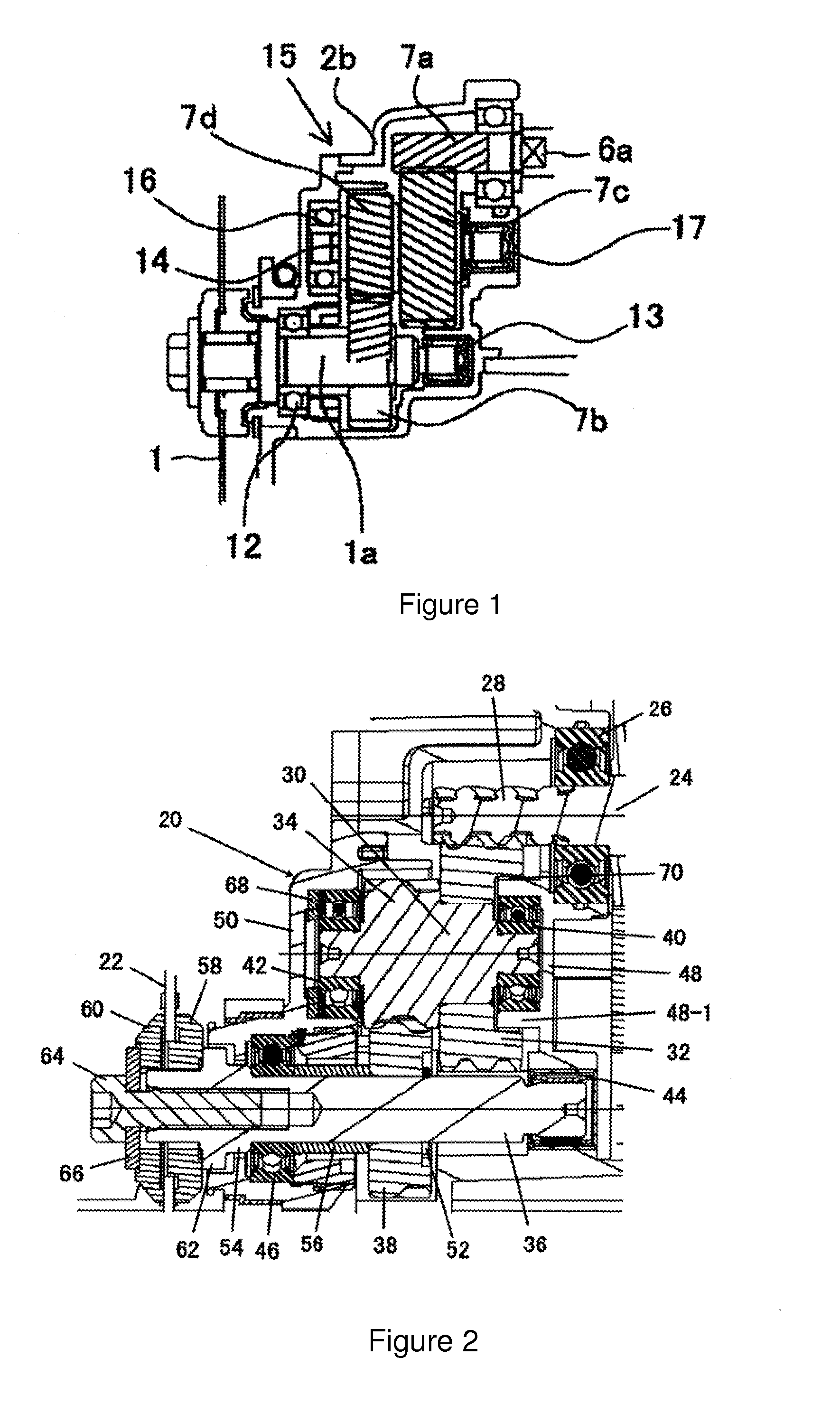
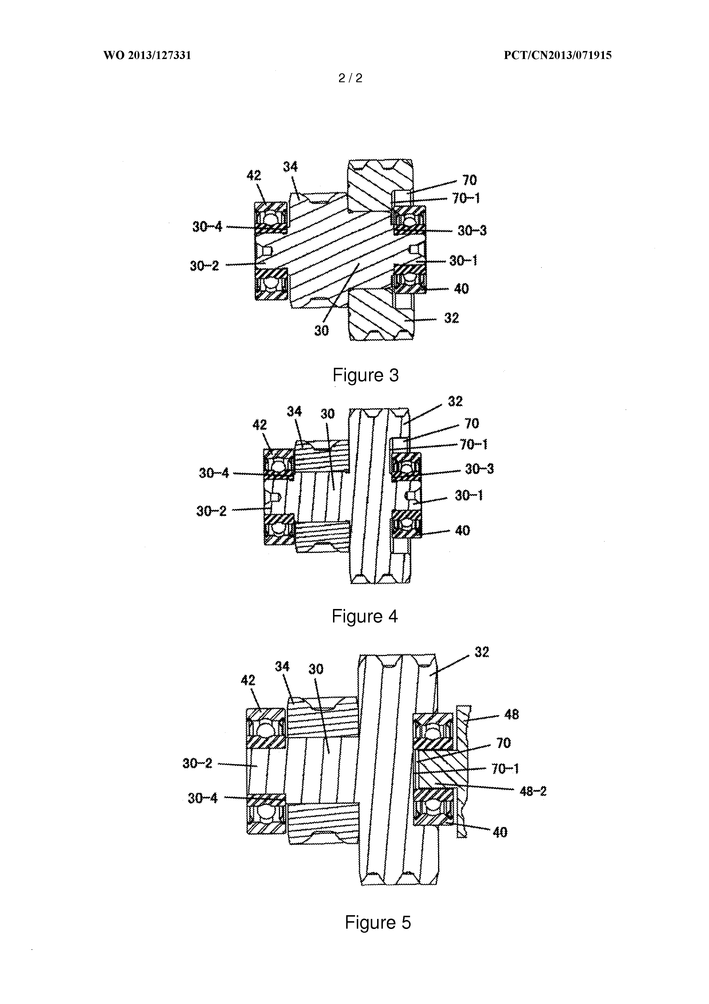
[0021]FIG. 2 shows a portion of a circular saw (for example, a portable circular saw) according to a preferred embodiment of the disclosure. The circular saw comprises a housing 20, an electric motor (not shown) mounted in the housing 20, a saw blade (tool bit) 22 mounted at least partially outside the housing 20, and a transmission for transmitting the rotational movement and torque of the electric motor to the saw blade. The electric motor has a motor shaft 24 which is supported in the housing 20 by a bearing 26.

[0022]The ...


PUM

PropertyMeasurementUnit
transmissionaaaaaaaaaa
axial forceaaaaaaaaaa
radial forceaaaaaaaaaa

Abstract

The disclosure relates to a transmission for a power tool, comprising an input gear driven by a driver, an intermediate shaft carrying first and second intermediate gears, the first intermediate gear being meshed with the input gear, an output shaft carrying an output gear, the output gear being meshed with the second intermediate gear for driving a tool bit, and proximal and distal bearings supporting proximal and distal ends of the intermediate shaft respectively. The first intermediate gear is formed with a receptacle portion which is recessed from a proximal end surface of the first intermediate gear in an axial direction towards a distal side, the proximal bearing being received in the receptacle portion at least in part in the axial direction. The disclosure also relates to a power tool comprising the above transmission. The disclosure provides a compact and robust structure.

Description

TECHNICAL FIELD[0001]The disclosure relates to a transmission used in a power tool, and to a power tool, in particular an electric cutting tool, comprising such a transmission.BACKGROUND ART[0002]A power tool, such as an electric cutting tool, generally comprises an electric motor, a tool bit (for example, a cutting blade) and a transmission for transmitting a force between the electric motor and the tool bit. The transmission generally comprises a gear transmission mechanism for transmitting the output rotational movement of the electric motor to the tool bit at a certain transmission ratio. For achieving a sufficient transmission ratio, the gear transmission mechanism is generally of the type of dual-stage or multi-stage, so that the sizes and positions of the gears can be set properly. However, more stages of the gear transmission mechanism result in a lager size of it. The gears, the shafts and the bearings of the gear transmission mechanism should be arranged in a compact manne...

Claims


Application Information

Patent Timeline
Patent Type & Authority Applications(United States)
IPC IPC(8): B23D47/12B25F5/00B23D45/16F16H57/021
CPCB23D47/12B23D45/16B25F5/001F16H57/021F16H1/20Y10T74/19642
Inventor YAN, YOUMEIZHEN, BOWANG, AIGUI
Owner BOSCH POWER TOOLS CHINA
Learn More