
Passive Alarm To Prevent Buried Infrastructure Damage

a technology of buried infrastructure and passive alarm, which is applied in the direction of pipe laying and repair, mechanical equipment, instruments, etc., can solve the problems of only practical system which requires continuous buried devices, endanger buried infrastructure, etc., and achieve the effect of convenient use and convenient protection of existing buried infrastructur

Active Publication Date: 2015-05-14
EAS IP LLC
View PDF6 Cites 5 Cited by
  • Summary
  • Abstract
  • Description
  • Claims
  • Application Information

AI Technical Summary

Benefits of technology

The patent text discusses three current solutions for protecting underground utilities from excavation damage: systems that require a proactive excavation crew, passive visual indicators, and monitored video and sensor systems. The invention described in the text is a modification of the passive visual indicator category, which allows for multiple, discrete alert modules to be buried near the buried infrastructure for added protection. This system can be used with both new construction and existing infrastructure. The technical effect of this invention is to provide a more efficient and effective way to protect underground utilities from excavation damage.

Problems solved by technology

Any system which requires a continuous buried device is only practical for new construction.
The excavation-sensing modules will be triggered during excavation that could endanger the buried infrastructure.

Method used


Image

  • Passive Alarm To Prevent Buried Infrastructure Damage
  • Passive Alarm To Prevent Buried Infrastructure Damage
  • Passive Alarm To Prevent Buried Infrastructure Damage

Examples


first embodiment

[0138]FIG. 7 shows a buried infrastructure excavation-sensing module 50 comprising an elongated, hollow tube 51 which is closed at both ends and scored at multiple locations 52 along the length of the tube. Tube 51 can be of any desired length and / or diameter. Although many different materials may be used for the tube 51, it has been found that thermoplastic pipe works quite well. An embodiment which was tested and found to be satisfactory was made from standard PVC pipe. The tested embodiment had an internal diameter of 1.5 inches with triangular scores spaced at approximately 1.5 inches locations along the length of the tube. Scoring makes the tube predictably breakable by external force. Other scoring geometries are also possible. The exact length and diameter of the buried infrastructure excavation-sensing module will depend on many different factors as will be readily apparent to one skilled in the art. For example, the composition of the soil where the infrastructure is buried...

fourth embodiment

[0143]FIG. 12 shows a cross-section of a buried infrastructure excavation-sensing module 90 comprising a gas-impermeable housing 91 that can be broken or ruptured by contact with construction equipment (not shown). The general configuration of excavation-sensing module 90 may be spherical or cylindrical as shown herein, or any other suitable shape. A compressed, colored and odorous gas 92 is contained in housing 91. A break in housing 91 will release colored, odorous gas 92, thus alerting construction personnel to the presence of the buried infrastructure. Housing 91 may be made of any suitable material such as a synthetic resin or plastic compound (as shown in the drawing) or a metallic substance. As an alternative to using a compressed, colored and odorous gas 92 within housing 91, it is possible to have a chemical compound contained within the housing 91 which will generate gas upon exposure to the atmosphere.

fifth embodiment

[0144]FIG. 13 shows a cross-section of a buried infrastructure excavation-sensing module 93 comprising a gas-impermeable outer housing 95 that can be broken or ruptured by construction equipment (not shown) and a second, inner gas-impermeable housing 97. As with the embodiment of FIG. 12, the general configuration of excavation-sensing module 93 may be spherical or cylindrical, as shown herein, or any other suitable shape. Housings 95 and 97 are held in spaced alignment by partitions 99. Both housings are filled with compressed, colored, odorous gas 101. The gas contained within housing 97 is at a higher pressure than the gas inside housing 95. A whistle 103 is mounted on inner housing 97, but is blocked by a friable diaphragm. When compressed, colored, odorous gas 101 is released from the outer housing 95 by an excavation-caused rupture, the gas inside housing 97 breaks the diaphragm causing the compressed, colored, odorous gas 101 to be released from inner housing 97 via whistle 1...


PUM


Abstract

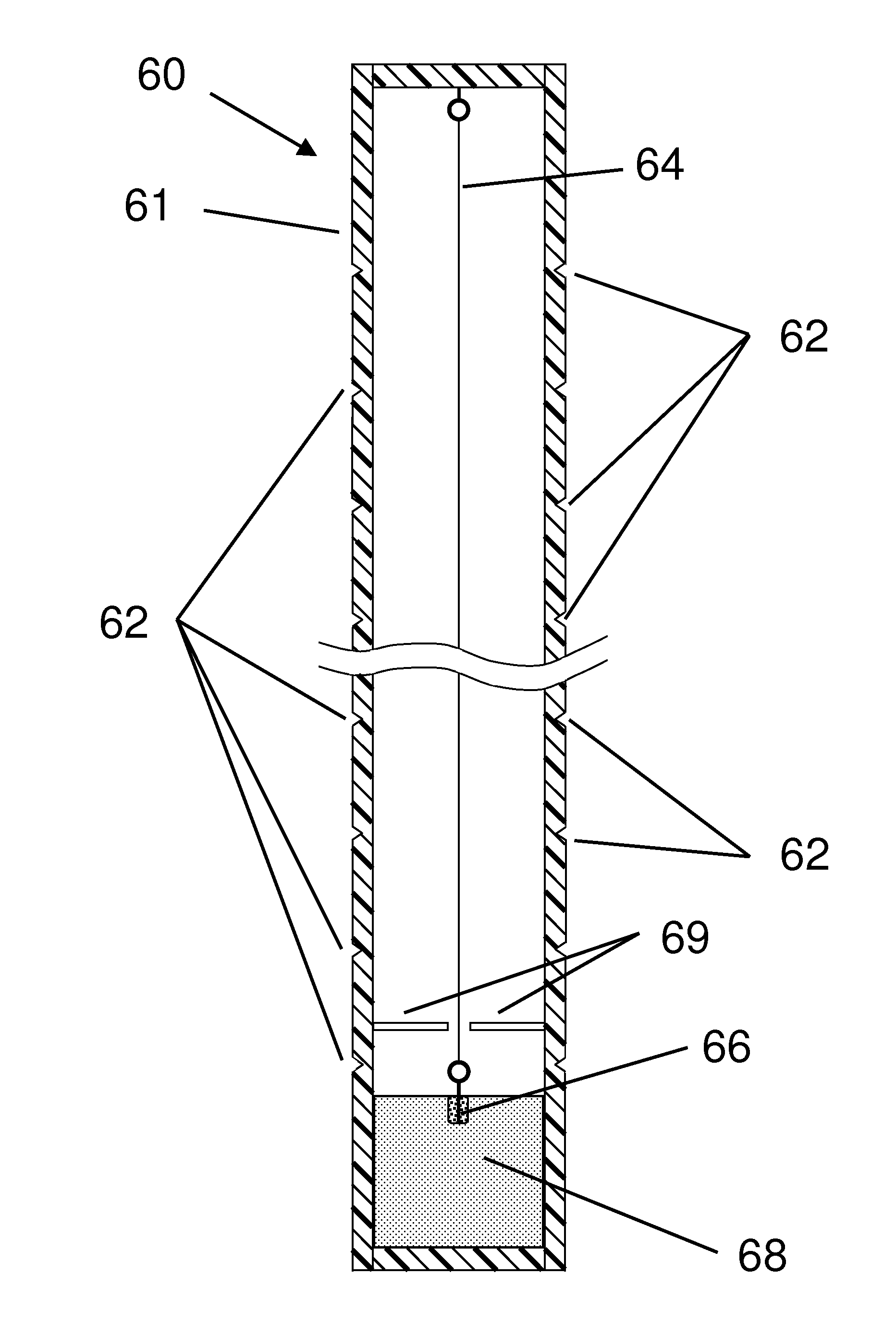
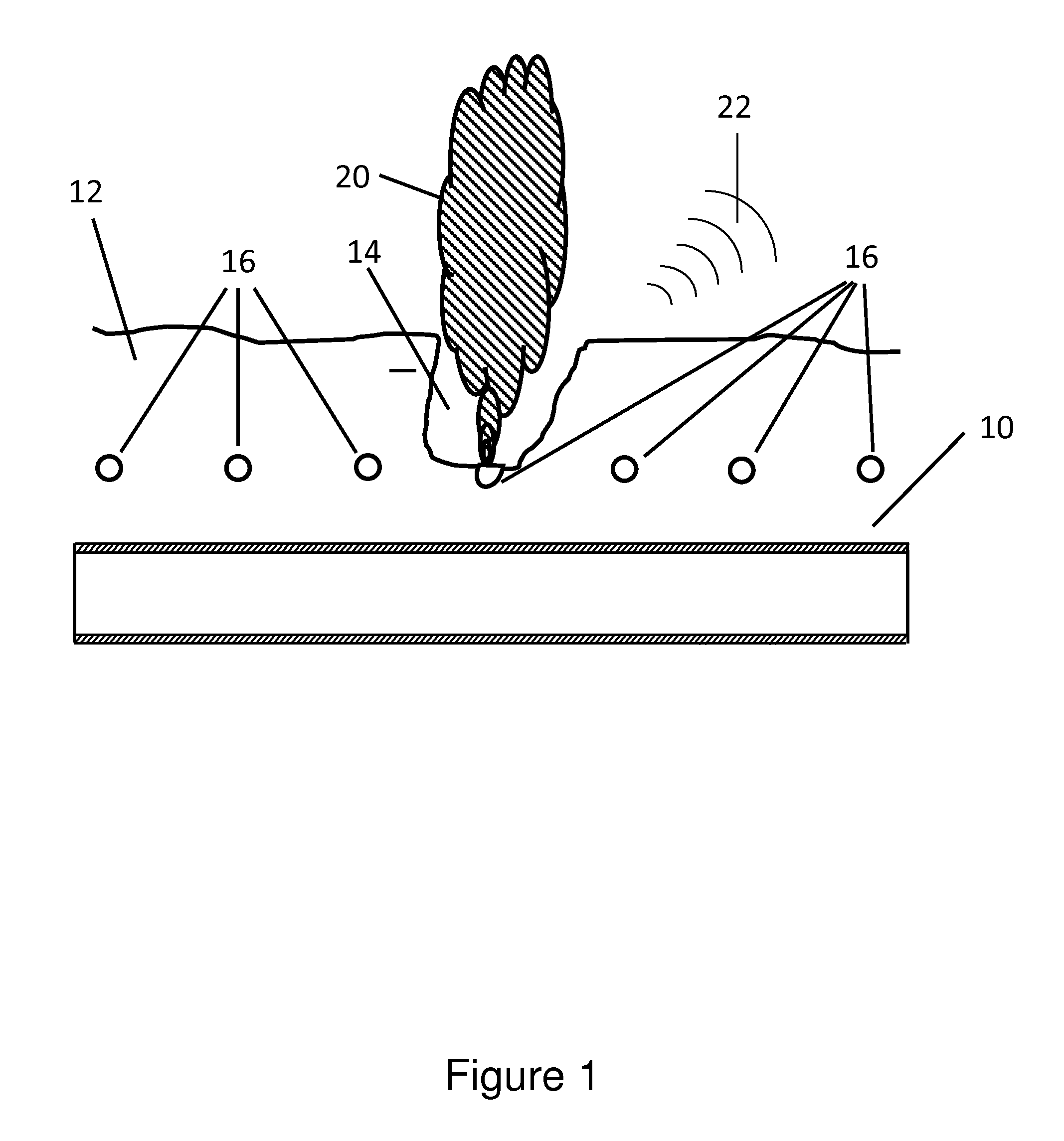
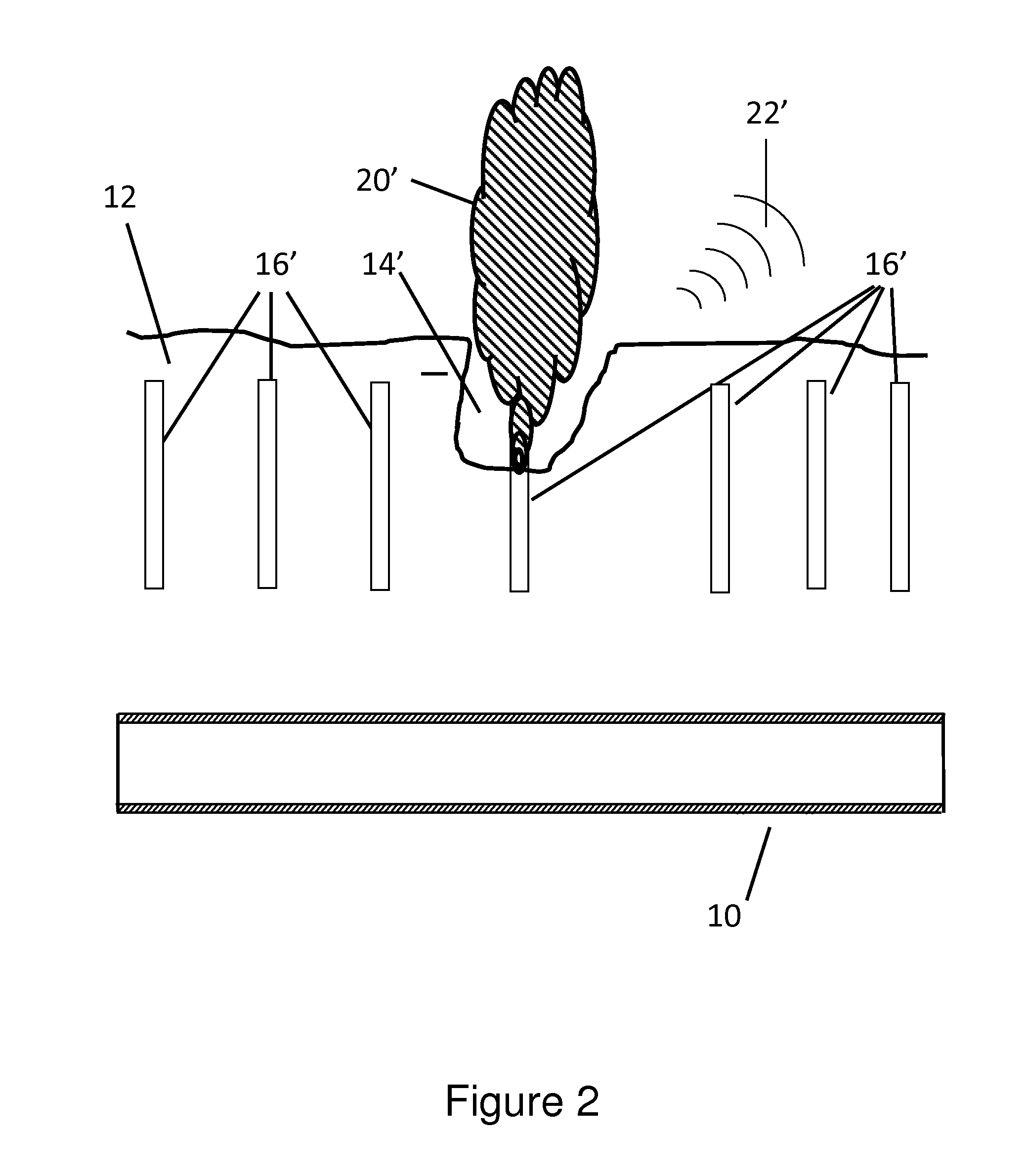
A method and apparatus are disclosed for preventing excavation damage to buried infrastructure. A plurality of excavation-sensing modules is buried near the buried infrastructure. The modules protect buried infrastructure by emitting dense clouds of highly visible gas when the modules are activated by impact with excavation equipment. In most cases the visible gas will be brightly colored and it may also have a strong odor and may produce a loud sound when the module is activated. The dense clouds of highly visible gas, the optional odor and loud sound alert construction crews or other workers that their excavation is nearing a protected underground structure. Once installed, no maintenance or active monitoring is required. In a preferred embodiment of the excavation-sensing module, the dense cloud of highly visible gas is produced by ignition of a smoke grenade within the module. In the preferred embodiment, the smoke grenade is ignited by the interaction of the excavator striking and breaking the buried module. Also in the preferred embodiment, the excavator will normally pull the ignited smoke grenade out of the buried module and to the surface increasing the visibility of the gas. Also in the preferred embodiment, a more reliable design for ignition of the smoke grenade is disclosed.

Description

CROSS-REFERENCE TO RELATED APPLICATIONS[0001]This application is a Continuation-In-Part of U.S. Ser. No. 14 / 367,888 which was filed as PCT / US2012 / 071096 on Dec. 20, 2102 and the instant application further claims the benefit of 61 / 578,698 filed on Dec. 21, 2011. The instant application incorporates by reference the disclosures of PCT / US2012 / 071096 and 61 / 578,698.BACKGROUND OF THE INVENTION[0002]Much of the nation's infrastructure is buried, including underground storage tanks, pipelines, power cables, and communication lines. The locations of these are not usually marked on the surface and are subject to excavation damage if a construction crew is not aware of their exact locations or if an operator is careless. For example, an extensive network of critical pipeline infrastructure delivers gas and oil throughout the United States. Recent natural gas and petroleum industry incidents have drawn renewed attention to the topic of pipeline safety. While construction crews are required to...

Claims


Application Information

Patent Timeline
IPC IPC(8): F42B12/48
CPCF42B12/48F16L1/11F42B23/00
Inventor DUNN, RYAN C.TUBBS, DONALD A.
Owner EAS IP LLC
Learn More