Methods utilizing polyamide-poly(phenylene ether) compositions

a technology of polyamide and phenylene ether, which is applied in the field of methods utilizing polyamidepoly (phenylene ether) compositions, can solve the problems that the polyamide-poly(phenylene ether) blends have not achieved widespread application in other aspects of the oil and gas industry

Inactive Publication Date: 2015-05-14
SABIC GLOBAL TECH BV
View PDF0 Cites 20 Cited by
  • Summary
  • Abstract
  • Description
  • Claims
  • Application Information

AI Technical Summary

Benefits of technology

[0005]a method of increasing the conductivity of a propped fracture, the method comprising introducing a proppant into the fracture to form the propped fracture, wherein the proppant comprises the polyamide-poly(phenylene ether) composition; and introducing a displacement fluid into the propped fracture, thereby displacing a portion of the proppant and forming additional channels for flow of formation fluids;
[0006]a method of decreasing the conductivity of a fluid loss zone, the method comprising introducing into the fluid loss zone particles comprising the polyamide-poly(phenylene ether) composition; and introducing into the fluid loss zone a fluid capable of swelling the particles, thereby reducing the conductivity of the fluid loss zone;
[0011]a method of reducing the production of particulate material from a well that traverses a hydrocarbon-bearing subterranean formation, the method comprising introducing to well a swellable filter medium comprising the polyamide-poly(phenylene ether) composition, the swellable filter medium being operable to allow fluid flow and reduce flow of particulates having a predetermined size;
[0012]a method of preventing fluid flow past a tapered face of a mill diverter in a wellbore, the method comprising: positioning the mill diverter in the wellbore, wherein the mill diverter comprises a body, the tapered face of which is located at one end of the body, and a swellable material comprising the polyamide-poly(phenylene ether) composition and being positioned circumferentially around the body of the mill diverter adjacent to the tapered face; and contacting the swellable material with a swelling fluid, thereby swelling the swellable material and preventing substantially all fluids from flowing past the swellable material after the swellable material has swelled;

Problems solved by technology

However, polyamide-poly(phenylene ether) blends have not achieved widespread application in other aspects of the oil and gas industry.

Method used


Image

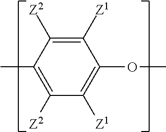
  • Methods utilizing polyamide-poly(phenylene ether) compositions
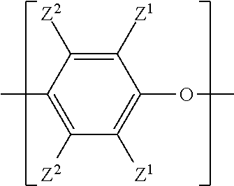
  • Methods utilizing polyamide-poly(phenylene ether) compositions
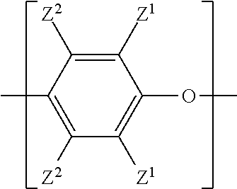
  • Methods utilizing polyamide-poly(phenylene ether) compositions

Examples


examples 1-5

[0092]These examples illustrate variations in the polyamide-poly(phenylene ether) composition. Components used to form the compositions are summarized in Table 1.

TABLE 1ComponentDescriptionPPE 0.40Poly(2,6-dimethyl-1,4-phenylene ether), CAS Reg. No. 25134-01-4,having an intrinsic viscosity of about 0.40 deciliter per gram as measured inchloroform at 25° C.; available as PPO ™ 640 from SABIC InnovativePlastics.PPE 0.45Poly(2,6-dimethyl-1,4-phenylene ether), CAS Reg. No. 25134-01-4,having an intrinsic viscosity of about 0.45 deciliter per gram as measured inchloroform at 25° C.; available as PPO ™ 800 from SABIC InnovativePlastics.PAPolyamide-6,6, CAS Reg. No. 32131-17-2, having a viscosity of about 126milliliters / gram measured in 90% formic acid according to ISO 307;available as STABAMID ™ 24 FE 1 from Rhodia.SBSButadiene-styrene block copolymer, CAS Reg. No. 9003-55-8, having apolystyrene content of about 30% and a melt flow index of about 5grams / 10 minutes, measured according to AS...


PUM

PropertyMeasurementUnit
weight percentaaaaaaaaaa

Abstract

A polyamide-poly(phenylene ether) composition includes, based on the total weight of the composition, 35 to 80 weight percent of polyamide, and 20 to 65 weight percent of a poly(phenylene ether). The polyamide-poly(phenylene ether) composition is utilized in a variety of methods, including methods applicable to the oil and gas industry.

Description

BACKGROUND OF THE INVENTION[0001]Polyamides or “nylons” are polymers used to make a wide variety of consumer goods, including women's stockings, parachutes, ropes, and components of automotive tires. Blends of polyamides with poly(phenylene ether)s combine the dimensional stability, low water absorption, and heat resistance of the poly(phenylene ether) with the chemical resistance and high melt flow of the polyamide.[0002]Recently, polyamide-poly(phenylene ether) blends have been used to form low density proppants for hydraulic fracturing. See, for example, U.S. Patent Application Publication No. US 2014 / 0349896 A1 of Bastuba et al. However, polyamide-poly(phenylene ether) blends have not achieved widespread application in other aspects of the oil and gas industry.BRIEF SUMMARY OF EMBODIMENTS OF THE INVENTION[0003]One embodiment is a method of utilizing a polyamide-poly(phenylene ether) composition, wherein the method is selected from the group consisting of[0004]a method of proppin...

Claims


Application Information

Patent Timeline
Patent Type & Authority Applications(United States)
IPC IPC(8): C09K8/80C09K8/52E21B43/26E21B17/02E21B33/138E21B43/04E21B47/00C09K8/588E21B43/267
CPCC09K8/80C09K8/588C09K8/52E21B43/26E21B17/02E21B33/138E21B43/04E21B47/00E21B43/267C09K8/467C09K8/502C09K8/5083C09K8/516C09K8/56C09K8/805C04B28/02C04B24/32C04B24/2652
Inventor BASTUBA, BRIANPOWALE, LAKSHMIKANT SURYAKANTHAGENAARS, ARNO C.HOSSAN, ROBERT JOHN
Owner SABIC GLOBAL TECH BV
Why Eureka
Try Eureka