
Pneumatic System And Process For Fracturing Rock In Geological Formations

Active Publication Date: 2015-05-14
ROCK HILL PROPULSION
View PDF16 Cites 11 Cited by
  • Summary
  • Abstract
  • Description
  • Claims
  • Application Information

AI Technical Summary

Benefits of technology

The patent describes a new system for extracting gas and oil from shale formations using pneumatic fracturing. This system is more environmentally friendly, uses less water, is less complex, and is more productive than previous methods. The system creates shock waves and shear waves that can improve the permeability of the shale formation, allowing for more effective oil and gas extraction.

Problems solved by technology

Typical hydraulic fracturing techniques also combine chemicals and debris with the water, which raises potential environmental concerns for the post-process water matrix.
The fracking process thus commonly not only requires great quantities of water and stored energy to pressurize the water but also requires the operator to clean the water after the hydraulic fracturing process is completed.
The water cleansing process is expensive and poses a logistical problem, particularly in remote areas of the country where hydraulic fracturing most commonly Occurs.
In addition, there has been much public opposition to hydraulic fracking due to perceived environmental hazards caused by fracturing rock, water usage, water contamination, and seismic activity.
Many of the chemicals used in fracking are not required to be identified by regulatory agencies, which causes concern that these unidentified chemicals are migrated into and polluting the ground water.
These environmental concerns have caused restraint of some fracking activities, particularly in foreign countries.
The hydraulic fracture can propagate vertically as well as laterally, however, as the water matrix seeks paths of least resistance.
Undesired vertical propagation has caused many hydraulic fractures to break out of the rock formation and penetrate aquifers and thief zones.
The steam injection process inherently requires a steam generation plant with attendant costly infrastructure footprint, equipment, energy, and manpower to operate.
Although the GasGun can be a more economical and effective alternative to hydraulic fracking, requires much less on-site equipment, and can replace small to medium hydraulic fracture treatments in particular, the applicants believe that the Gas Gun has limited effect in that the predetermined pressure pulse device and concept of operation is comparatively inefficient, time consuming, and unduly expensive due to the inability to readily vary the type of pulse with the Gas Gun.

Method used


Image

  • Pneumatic System And Process For Fracturing Rock In Geological Formations
  • Pneumatic System And Process For Fracturing Rock In Geological Formations
  • Pneumatic System And Process For Fracturing Rock In Geological Formations

Examples


example 1

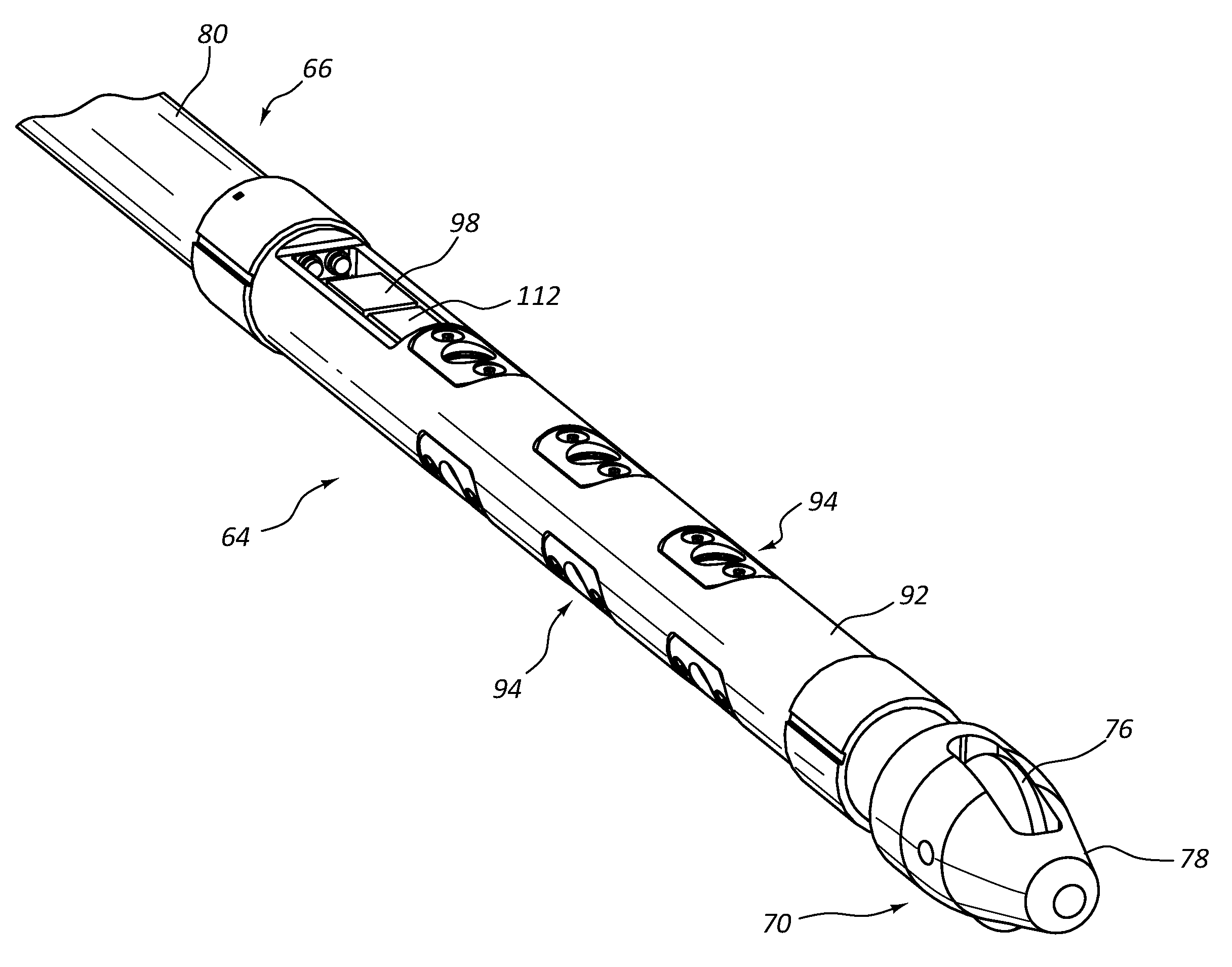
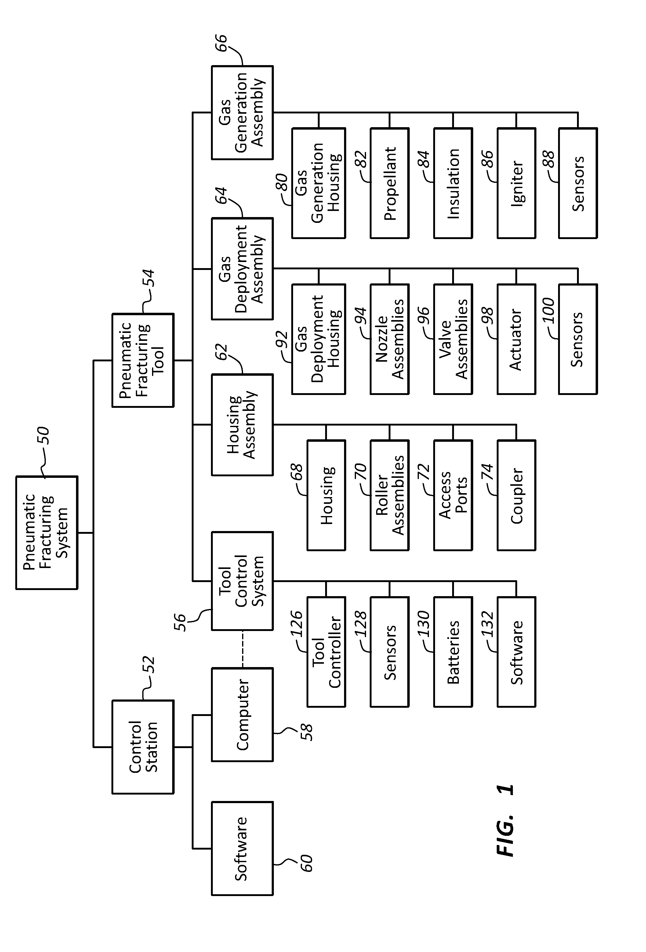
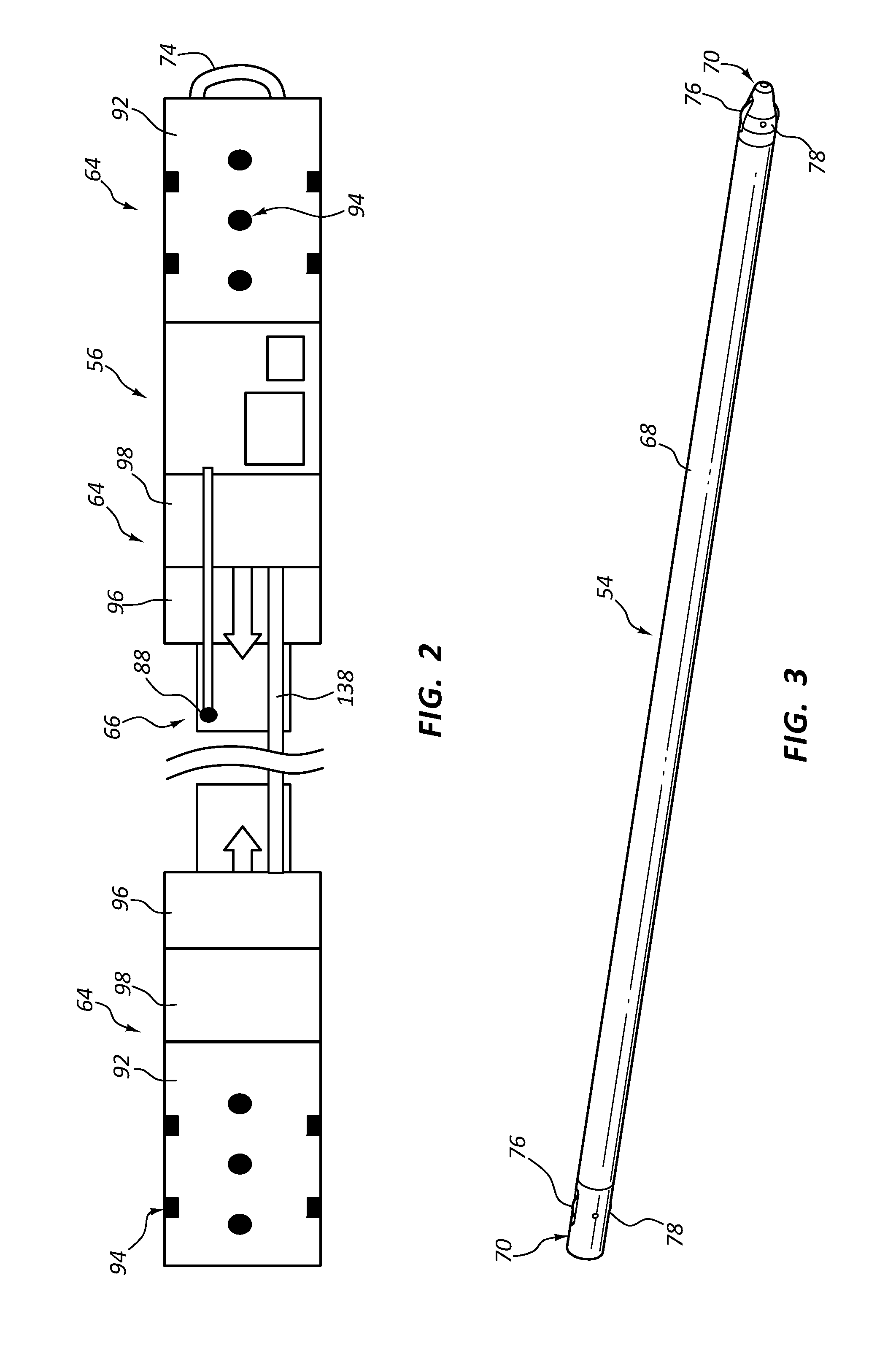
[0188]The following is a detailed step by step process that can be used to fracture a rock formation using the pneumatic fracturing system 50. The first step is to ship and setup the pneumatic fracturing system 50 hardware and energetics (e.g., propellant, explosive charges, and the like). The control station is transported to the job site by the operator. The inert components of the pneumatic fracturing tool 54 are transported from the manufacturing facility to the job site using a commercial transport company.

[0189]The energetic components of the pneumatic fracturing tool 54 (i.e., propellant, igniter, explosive charges, and the like) are shipped separately from the inert components by trained personnel. The energetic components are combined with the inert components at the job site. The pneumatic fracturing tool 54 is stored at the job site in an explosive magazine until it is ready to be deployed by trained personnel. The pneumatic fracturing tool 54 is stored in a manual safe c...

example 2

[0194]A ballistic dynamic simulation of the hot gas valve and electromechanical actuation was performed using Matlab Simulink software. The simulation parameters are shown in FIGS. 23-24. The simulation examined the first pulse of both the “soft” and “hard” rock extreme duty cycle cases (described above). The results showed that with the propellant ballistic properties, design volumes / geometries, and actuator performance characteristics noted in the FIGS. 25-26, the system is controllable and representative pressure and amplitude profiles can be realized that match the requirements for the extreme rock formation fracturing cases. Overall, FIGS. 23-26 show the results of the ballistic dynamic simulation that collectively specify the dynamic requirement for the hot gas valve and electromechanical actuation.

[0195]It should be appreciated that some components, features, and / or configurations may be described in connection with only one particular embodiment, but these same components, f...


PUM


Abstract

A tunable pneumatic fracturing system and process useable in some instances to extract oil and gas. Some embodiments provide a pneumatic fracturing tool with an elongated body that (a) contains (i) a propellant supply source intermediate opposed propellant gas discharge assemblies, (ii) a control system, and (iii) a communications port, and (b) has roller assemblies at opposed ends of the body. The tool can be tuned to provide gas pulse amplitudes and frequencies that react with the resonant frequency or other aspect of an adjacent earth formation. Some tool embodiments can variably sweep a rock formation and adjust the pressure pulse amplitude and frequency to disrupt the formation in a more productive manner. Some tools can penetrate vertical bore wells as well non-vertical bore wells. In some systems, the tool is transported and operated by a control truck and can be commanded to download operational data during or after use.

Description

CROSS-REFERENCE TO RELATED PATENT APPLICATIONS[0001]This claims the benefit of U.S. Provisional Pat. App. No. 61 / 901,916, titled “Pneumatic Shearing Tool, System, and Method of Use,” filed on 8 Nov. 2013, and U.S. Provisional Pat. App. No. 61 / 901,922, titled “Pneumatic Shearing Tool, System, and Method of Use,” filed on 8 Nov. 2013, the entire contents of which are incorporated by reference into this document. In the event of a conflict, the subject matter explicitly recited or shown in this document controls over any subject matter incorporated by reference. The incorporated subject matter should not be used to limit or narrow the scope of the explicitly recited or depicted subject matter.APPLICANTS' VIEW OF SOME ASPECTS OF THE PRIOR ART[0002]Hydraulic fracturing (“fracking”) has long been used in conjunction with deep well horizontal drilling and well completion techniques to procure oil, gas, and geothermal fluid. Fracking refers to the procedure of creating fractures in rocks an...

Claims


Application Information

Patent Timeline
IPC IPC(8): E21B43/26E21B47/12E21B43/00E21B43/16
CPCE21B43/26E21B43/00E21B47/12E21B43/168E21B43/263E21B43/2605
Inventor CARLSON, RUSSELL W.SNOW, JOHN H.BARR, DUSTIN C.
Owner ROCK HILL PROPULSION
Features
  • Generate Ideas
  • Intellectual Property
  • Life Sciences
  • Materials
  • Tech Scout
  • Unparalleled Data Quality
  • Higher Quality Content
  • 60% Fewer Hallucinations
Learn More