Power converter for powering an MRI gradient coil and method of operating a power converter

Inactive Publication Date: 2015-05-14
KONINKLJIJKE PHILIPS NV
View PDF3 Cites 10 Cited by
  • Summary
  • Abstract
  • Description
  • Claims
  • Application Information

AI Technical Summary

Benefits of technology

The present invention is about a power converter for powering a gradient coil of a magnetic resonance (MR) examination system. The technical effects of the invention include: advantageous amplification of the gradient current ripple to improve image quality; effective suppression of higher harmonics to enhance image quality; flexibility to use different filter settings to achieve desired image quality; and utilization of identical switching cells for efficient power conversion. These technical effects contribute to the improvement of the overall performance and quality of MR examination systems.

Problems solved by technology

Moreover, such high frequencies can lead to smaller inductive and capacitive storage elements, thereby reducing system size, weight, and cost.
Practical semiconductor power switches feature a certain energy loss for every switching event.
However, frequencies in excess of the indicated levels lead to increased dissipation in the device, thereby to low circuit efficiency, and in the limit to an unworkable circuit.
Additionally, due to the circuit geometry, additional inductances such as connecting wires and bus bars are introduced in the circuit which can in most cases not be made completely equal among cells in an economically reasonable effort.
Exploiting the full potential of an interleaving concept is therefore not possible for high values of N at reasonable cost.
This method leads to some suppression, but in general not to complete annihilation, of the fundamental switching frequency.

Method used


Image

  • Power converter for powering an MRI gradient coil and method of operating a power converter
  • Power converter for powering an MRI gradient coil and method of operating a power converter
  • Power converter for powering an MRI gradient coil and method of operating a power converter

Examples


Embodiment Construction

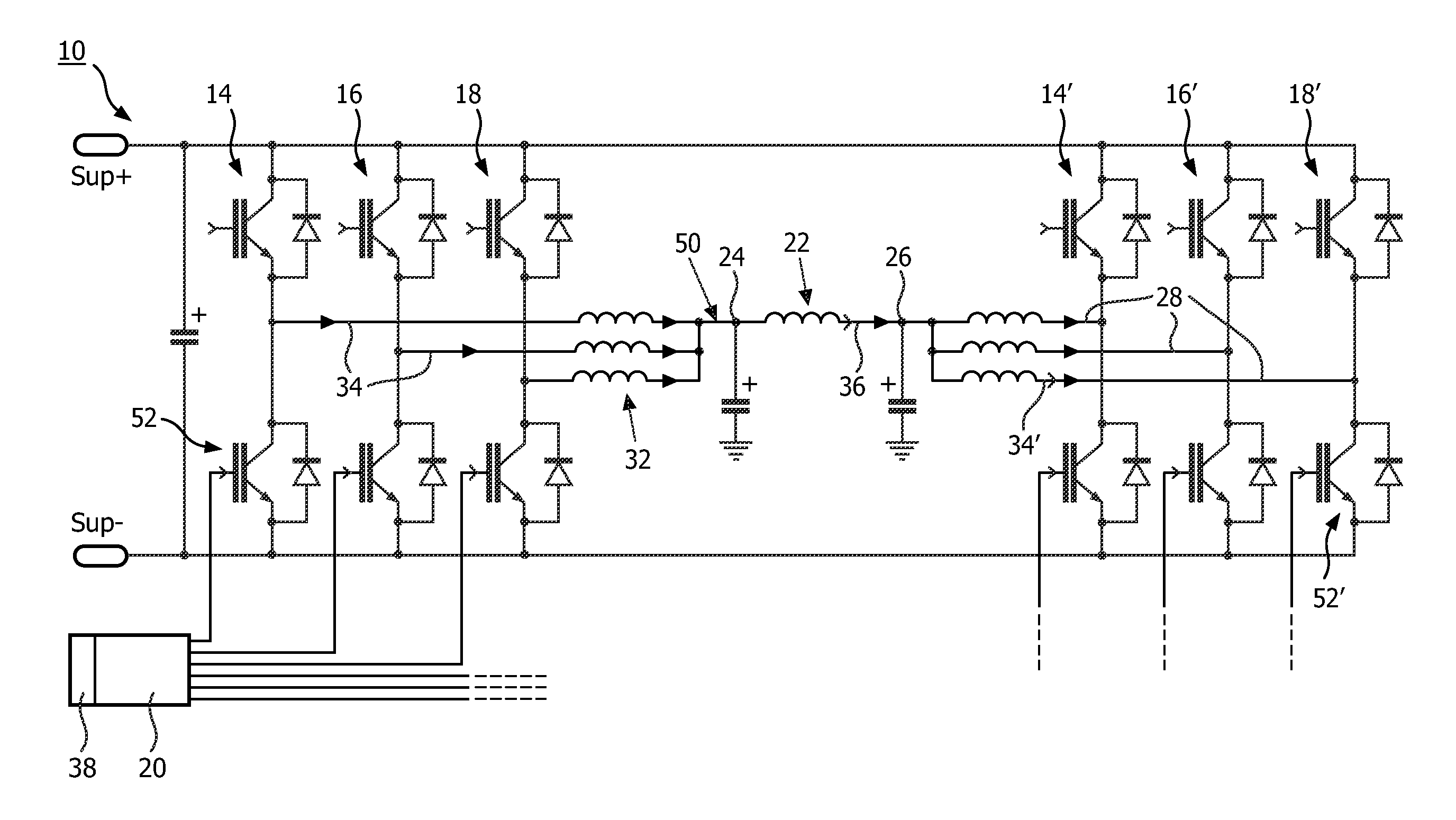
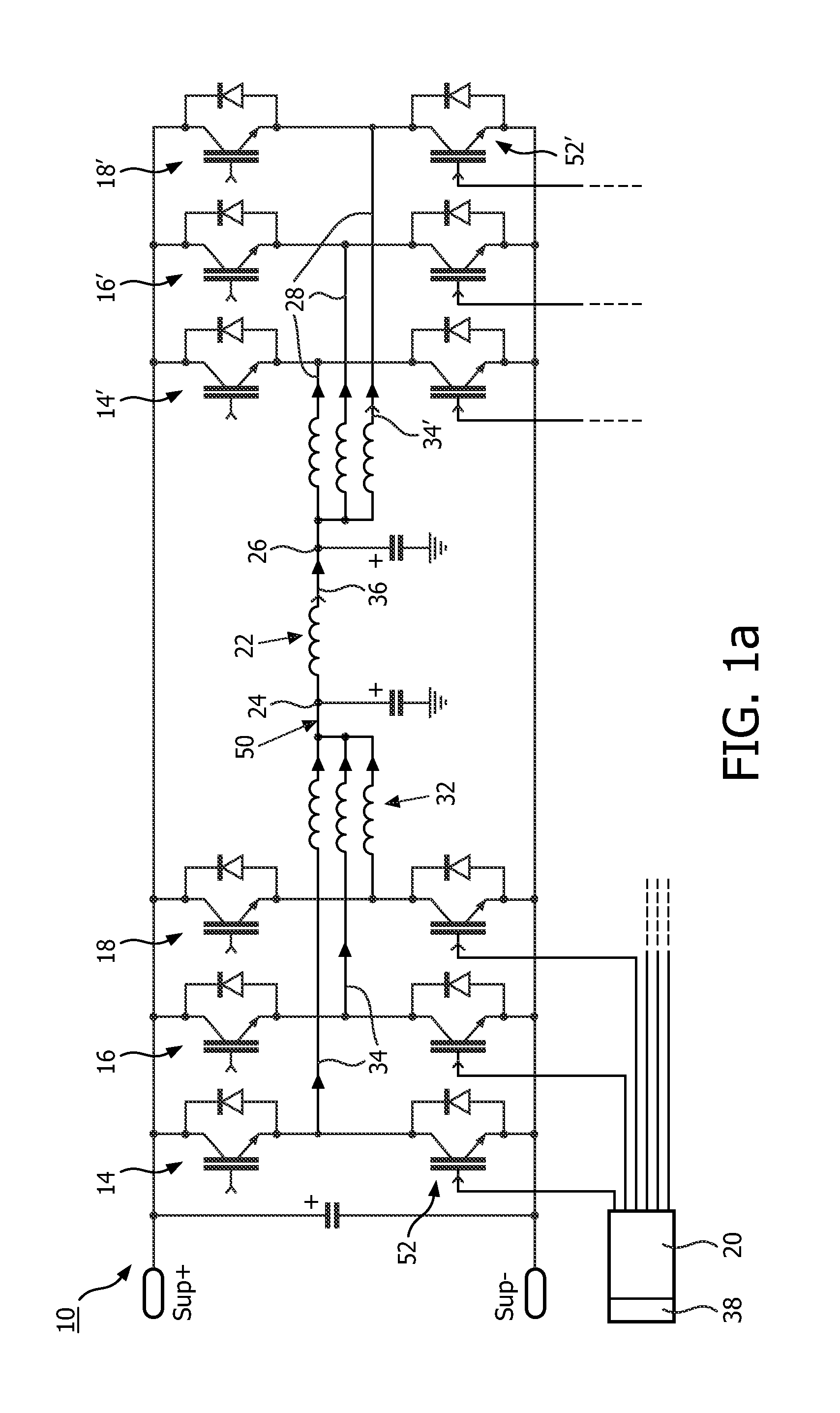
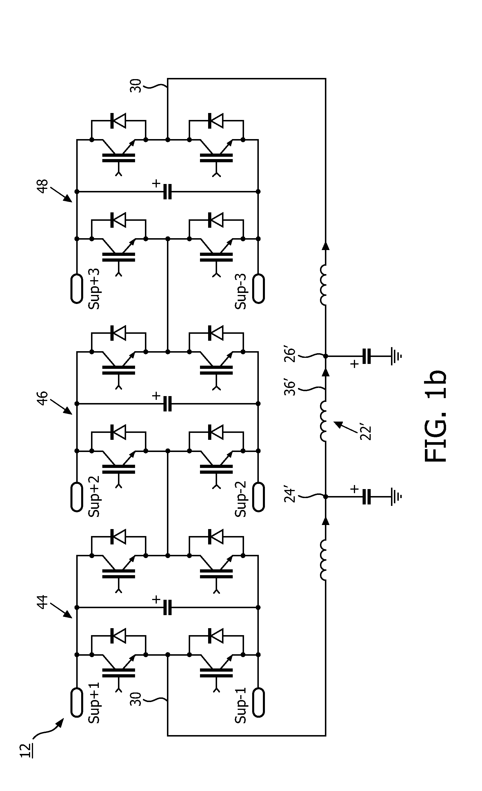
[0042]FIGS. 1a and 1b show embodiments of gradient coil units in accordance with the invention. The gradient coil units comprise a power converter of an interleaved configuration 10 (FIG. 1a) and another power converter of multilevel configuration 12 (FIG. 1b), respectively. In the sequel, the interleaved configuration 10 will be used in the description of the embodiments, but the invention can also be applied to power converters of multilevel configuration 12.

[0043]The power converters comprise three essentially identical switching cells 14, 16, 18 that are designed as an H bridge with four switching members 52 formed by semiconductor switches, antiparallel diodes, an inductor 32 and a filter, as commonly known by the one of skills in the art. The switching members 52 are provided to switch between a conducting state configuration and an essentially non-conducting state configuration, and the switching cells 14, 16, 18 are provided to switch at at least a fundamental switching freq...


PUM


Abstract

A power converter for powering a gradient coil (22) of a magnetic resonance examination system, comprising: a plurality of essentially identical switching cells (14, 16, 18), each switching cell (14, 16, 18) having a plurality of switching members (52) that are provided to switch between a conducting state configuration and an essentially non-conducting state configuration, and the switching cells (14, 16, 18) being provided to switch at at least a fundamental switching frequency fSW and in a pre-determined temporal relationship to each other, a pulse control unit (20) provided to control the pre-determined temporal relationship of switching of the switching cells (14, 16, 18) by providing switching pulses to the switching members (52) of the switching cells (14, 16, 18), wherein the pulse control unit (20) is provided to determine a correction for the pre-determined temporal relationship of the switching of the switching cells (14, 16, 18) from at least one electrical quantity each of each one of the plurality of switching cells (14, 16, 18), and to adjust the pre-determined temporal relationship according to the determined correction, such that at least one electrical quantity of a power converter output essentially has a zero amplitude at the fundamental switching frequency fSW; and a method of operating a power converter, particularly for powering a gradient coil (22) of a magnetic resonance examination system, for compensating inductance asymmetries.

Description

FIELD OF THE INVENTION [0001]The invention pertains to a power converter for powering a gradient coil of a magnetic resonance (MR) examination system and a method of operating a power converter for compensating inductance asymmetries.BACKGROUND OF THE INVENTION [0002]In the field of power converters it is known to employ semiconductor switches configured in switching cells that allow for different directions of current flow. The semiconductor switches are controlled by switching pulses of a fundamental switching frequency that are pulse width-modulated with a variable duty cycle.[0003]In many types of power converters it is desirable to attain an effective pulse width-modulation (PWM) frequency as high as possible. Such high frequencies are in general advantageous for attaining high reaction speed (high bandwidth) and accurate signal construction. Moreover, such high frequencies can lead to smaller inductive and capacitive storage elements, thereby reducing system size, weight, and ...

Claims


Application Information

Patent Timeline
IPC IPC(8): H02M7/5387G01R33/385G01R33/54H02M1/12
CPCH02M7/5387G01R33/543G01R33/385H02M1/12H02M7/53875H02M7/49H02M7/493G01R33/3852H02M1/0085H02M1/0043
Inventor HUISMAN, HENDRIKCARIS, MARCUS LEONARDUS ANNA
Owner KONINKLJIJKE PHILIPS NV
Why Eureka
Try Eureka