
Model eye producing a speckle pattern having a reduced bright-to-dark ratio for use with optical measurement system for cataract diagnostics

a technology of optical measurement system and model eye, which is applied in the field of optical measurement equipment, can solve the problems of measurement errors, optical measurement or analysis instruments, and speckled light patterns produced in instruments, and achieve the effect of reducing the bright-to-dark ratio

Inactive Publication Date: 2015-05-14
AMO WAVEFRONT SCI
View PDF4 Cites 10 Cited by
  • Summary
  • Abstract
  • Description
  • Claims
  • Application Information

AI Technical Summary

Benefits of technology

The patent text describes a model eye and a system for cataract diagnostics that use an optical measurement instrument to verify correct operation. The model eye has a speckle pattern that causes a reduced bright-to-dark ratio to improve the accuracy of the optical measurement instrument. The system includes the model eye and the optical measurement instrument, which can measure various characteristics of the eye, such as ocular biometry information, anterior corneal surface information, posterior corneal surface information, anterior lens surface information, posterior lens surface information, lens tilt information, and lens position information. The material structure provided at the rear planar surface of the optically transmissive structure of the model eye can have a plurality of layers, and the thickness of at least two of the layers can be measured to determine if the optical measurement instrument is operating properly. The system can also predict the optimal intraocular lens position based on the measured eye characteristics.

Problems solved by technology

An undesirable feature of the light sources used in some of these instruments is that the light pattern produced in the instrument is marred by speckle.
Speckle can cause problems with some optical measurement or analysis instruments.
For example, there are two ways that speckle causes measurement errors in an instrument that employs a Shack-Hartmann wavefront sensor.
One problem is that the mathematical algorithms called reconstructors that are employed by such instruments have fitting errors in data sets that contain dark regions of the speckle pattern.
Another problem is “intensity coupling.” Intensity coupling may occur when a wavefront sensor is constructed such that the lenslet array is not located exactly one focal length from the pixel array.
These shifts cause errors in the calculated wavefront.
Meanwhile, it is sometimes necessary to be able to verify correct operation and specified performance of an optical measurement instrument such those described above in an operational setting.
When a typical model eye is measured, however, the speckle is more severe than that typically seen when measuring a human eye.
The problem is further exacerbated by the fact that the “cornea” of the model eye acts like a magnifying glass and makes the structure of the bright spots and dark regions appear large on the detector inside the optical measurement instrument.
For all these reasons, these large variations in light level cause inaccurate measurements that can in turn affect diagnosis and treatment.

Method used


Image

  • Model eye producing a speckle pattern having a reduced bright-to-dark ratio for use with optical measurement system for cataract diagnostics
  • Model eye producing a speckle pattern having a reduced bright-to-dark ratio for use with optical measurement system for cataract diagnostics
  • Model eye producing a speckle pattern having a reduced bright-to-dark ratio for use with optical measurement system for cataract diagnostics

Examples


Embodiment Construction

[0051]Exemplary embodiments of model eyes and methods for verifying proper operation and performance of optical measurement equipment through use of a model eye will be described in some detail below so as to illustrate various aspects and advantages of these devices and methods. However, it should be understood that the principles involved in these devices and methods can be employed in a variety of other contexts, and therefore the novel devices and method disclosed and claimed here should not be construed as being limited to the example embodiments described below.

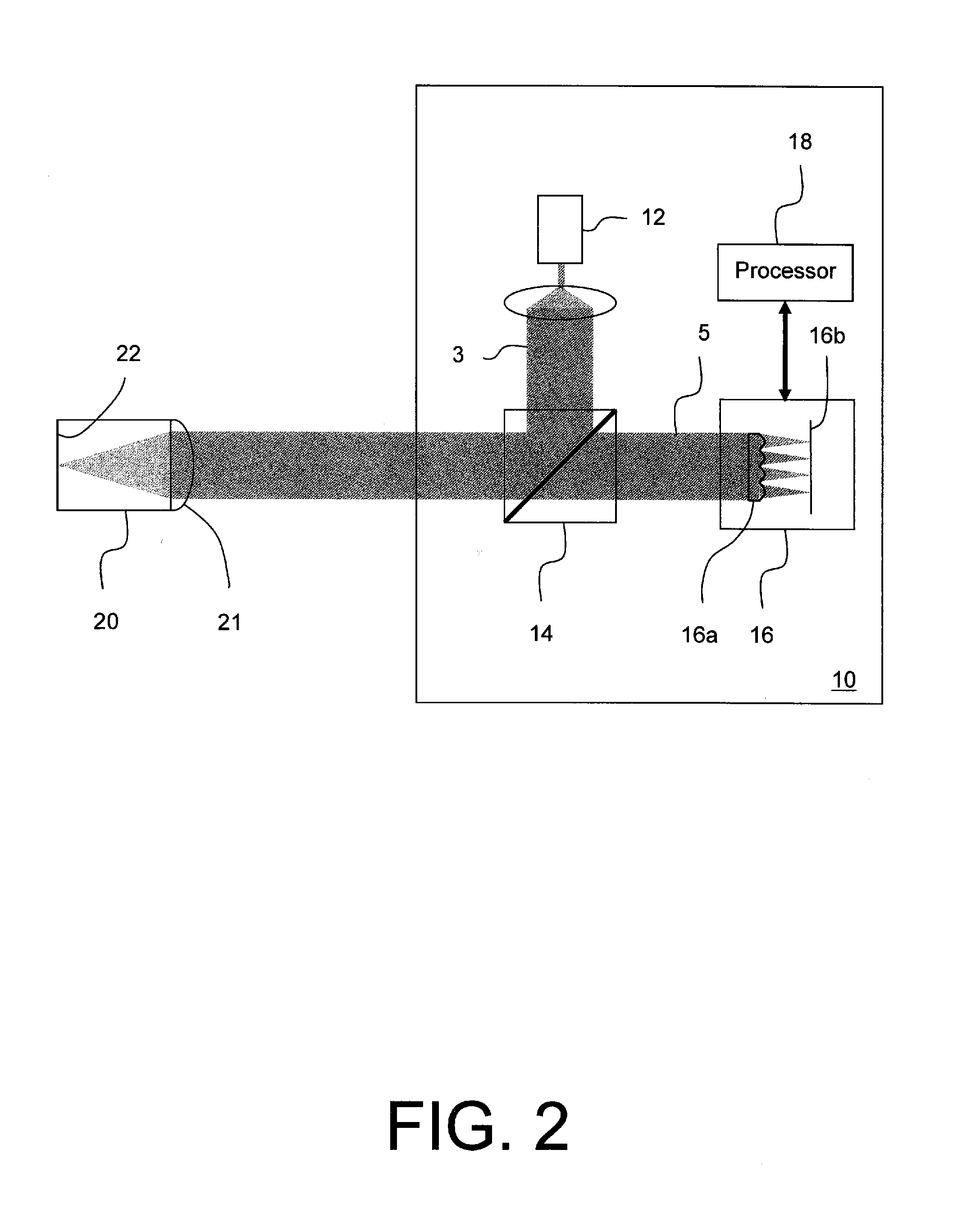
[0052]FIG. 2 illustrates an example of an optical measurement instrument 10 making a measurement with one example embodiment of a model eye 20 to verify correct operation and specified performance of an optical measurement instrument. Here optical measurement instrument 10 may be a wavefront aberrometer. Optical measurement instrument 10 includes, among other elements, a coherent light source (e.g., a laser or SLD) 12, ...


PUM


Abstract

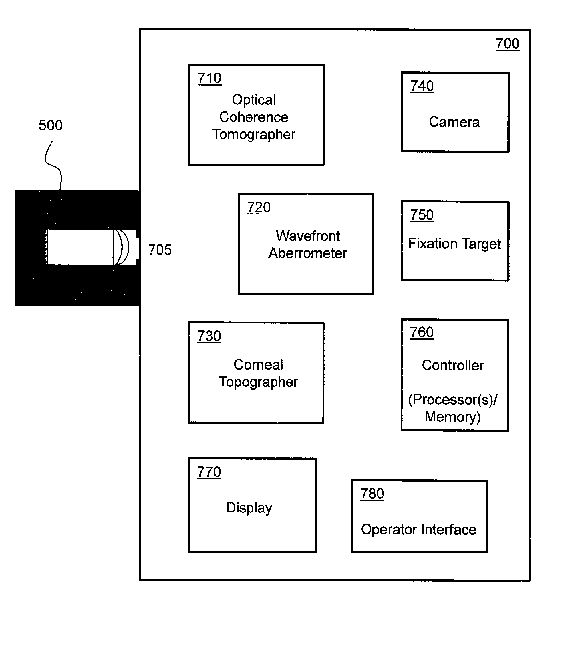
A system includes a model eye and an optical measurement instrument, which includes: a corneal topography subsystem; a wavefront sensor subsystem; and an eye structure imaging subsystem. The subsystems may have a common fixation axis, and be operatively coupled to each other via a controller. The optical measurement instrument may perform measurements of the model eye to verify correct operation of the optical measurement instrument for measuring one or more characteristics of a subject's eye. The model eye may include an optically transmissive structure having a front curved surface and an opposite rear planar surface, and a material structure provided at the rear planar surface of the optically transmissive structure and having a characteristic to cause a speckle pattern of a portion of a coherent light beam that is directed back out the front curved surface of the optically transmissive structure to have a bright-to-dark ratio of less than 2:1.

Description

CROSS-REFERENCES TO RELATED APPLICATIONS[0001]This patent application is a continuation-in-part of U.S. patent application Ser. No. 13 / 950,756, filed on 25 Jul. 2013, which is in turn a divisional of U.S. patent application Ser. No. 13 / 011,003, filed 21 Jan. 2011 and issued as U.S. Pat. No. 8,517,538, the entire contents of all of which are incorporated herein by reference.TECHNICAL FIELD[0002]Embodiments of this invention pertain to optical measurement equipment, and more particularly, to a model eye for verifying proper operation and performance of optical measurement equipment, including an optical measurement instrument for carrying out cataract diagnostics, and a method for verifying proper operation and performance of such optical measurement equipment with a model eye.BACKGROUND[0003]A number of optical measurement or analysis instruments use one or more light spots generated from coherent light sources, such as lasers or superluminescent diode (SLDs), to make optical measure...

Claims


Application Information

Patent Timeline
Patent Type & Authority Applications(United States)
IPC IPC(8): A61B3/00A61B3/107A61B3/10
CPCA61B3/0025A61B3/102A61B3/1005A61B3/107A61B3/1015A61B5/0066A61B2017/00716A61B2560/0233A61F2/14A61F2/142A61F2/16G02B27/48
Inventor COPLAND, RICHARD J.NEAL, DANIEL R.RAYMOND, THOMAS D.XIONG, WEIPULASKI, PAUL D.FARRER, STEPHEN W.VIDAL, CARMEN CANOVAS
Owner AMO WAVEFRONT SCI
Learn More