
Cell electric stimulator with separate electrodes for electrical field shaping and for stimulation

a cell electric stimulation and electrode technology, applied in the field of cell electric stimulation, can solve the problems of insufficient pumping efficiency, small pumping fraction, and inability to accurately predict the time delay of the electric pulse, and achieve the effect of saving pumping efficiency and reducing the cost of electric pulse delay

Inactive Publication Date: 2015-05-14
LEE CHONG IL +1
View PDF3 Cites 18 Cited by
  • Summary
  • Abstract
  • Description
  • Claims
  • Application Information

AI Technical Summary

Benefits of technology

The patent text discusses the need for a heart pacemaker that can maximize pumping efficiency and control the path and timing of the stimulating pulse in the heart muscle, including time delays between current injected from different locations on the surface of the stimulator. The invention discloses a mechanism to control what the patent calls the "vector current" and the relative time at different directions and places, as opposed to only its magnitude. The technical impact of the invention is to improve the control and efficiency of electrical stimulation in the heart and other organs.

Problems solved by technology

Unfortunately most hearts, even very good ones, fail to keep a good electrical pulse progression, resulting in non-optimal heart contraction and consequently in smaller pumping fraction (smaller volumetric fraction of the blood pumped forward).
It is worth to note that existing electrical stimulators (heart pacemakers and other stimulators too) also shape the electric field (any charge or voltage distribution does create some electric field around it), yet the field shaping due to the active electrodes is not done on purpose to achieve the best heart contracting sequence (or other purposes for other devices), because the active electrodes exist for the purpose of injecting electric charges, not to shape the electric field.
Incorrect time delays of the electric pulse are costly for the pumping efficiency, because they are the very cause of the muscle contraction, that is, of the pumping, and localized higher or lower resistivity are costly too, because they change the electric current intensity, which in turn decrease or increase the strength of the muscle contraction, that is, of the pumping pressure, either way decreasing the total pumping volume.
Granted that there are people that extract the toothpaste squeezing the tube from the middle, but it is universally acknowledged to be inefficient to do so, even by the very people that do it; they make a huge mess and drive other family members crazy trying to fix it all the time.
The inventors suspect that many a marriage ended in divorce because of such improperly squeezed toothpaste tubes.
It would be ideal if the heart squeezed as a properly used toothpaste tube, not as a collapsing air balloon that collapses upon itself from all directions at the same time, but alas, the heart is far from a good pump.
One of the reasons for the lack of appreciation of this sequential contraction is that it is not perfect, as if it occurred within a well-engineered pump.
Lastly, each half squeezes in ½ second, too short a time for a human being to perceive in detail.
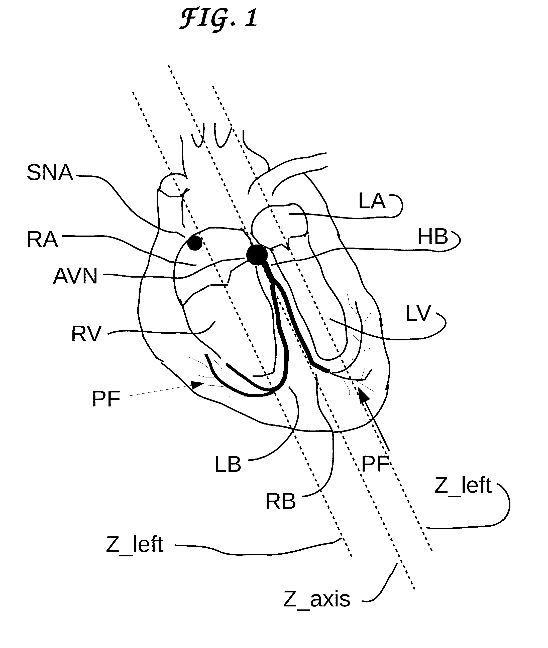
The ventricle, on the other hand, has both entrance and exit ports at its top, which poses a difficult problem to solve, needing as it does, to contract from bottom to top, to force the blood to exit at the top, while the electric pulse is coming from the top!
Firstly, that not only is the heart contraction caused by an electric pulse but also that this electrical pulse propagates relatively slowly through its muscles and special fibers, because it relies on the propagation of heavy ions in a viscous medium.
Mathematicians have goose bumps when they are presented with an inverse problem, because they know that most inverse problems have no solution (no closed form solution, to be precise), nor does this one.
Such a symmetric field fail to offer a maximum electrical stimulation in any case, particularly when the electric stimulator happens to have been implanted off-center.
More modern stimulators, e.g. the ones introduced by Sapiens Neuro and by Rubert Martens et al., “Spatial steering of deep brain stimulation volumes using a novel lead design” Clin. Naurophys. Vol 122 pg 558-566 (2011) are capable of creating an asymmetric electric charge distribution in the target area, but fail to decouple the control of the electric field from the injection of the electric charges, therefore failing to maximize the results.
Also the existing devices use large electrodes, which did not allow for precise control of the point of electric current injection.

Method used


Image

  • Cell electric stimulator with separate electrodes for electrical field shaping and for stimulation
  • Cell electric stimulator with separate electrodes for electrical field shaping and for stimulation
  • Cell electric stimulator with separate electrodes for electrical field shaping and for stimulation

Examples


Embodiment Construction

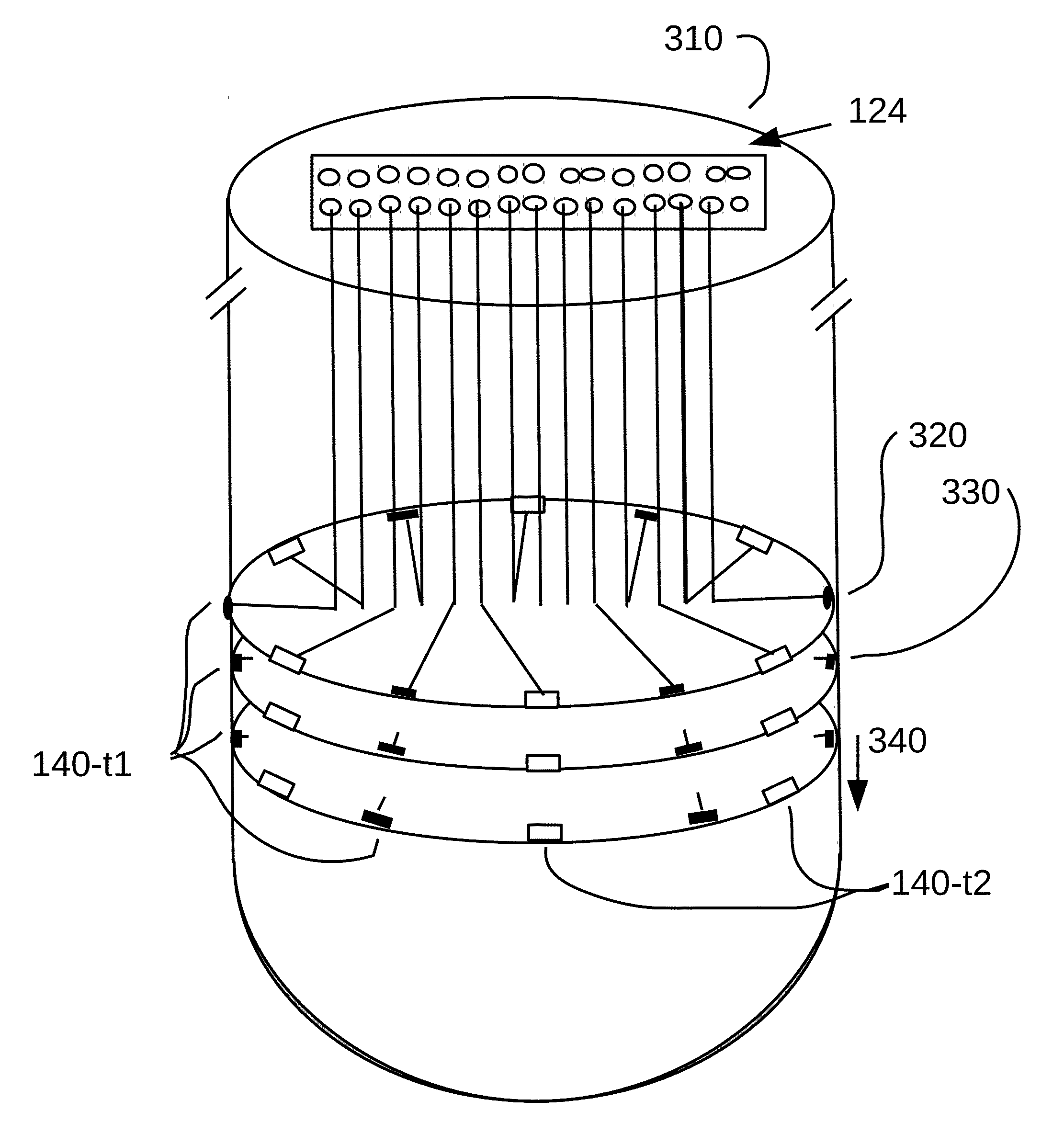
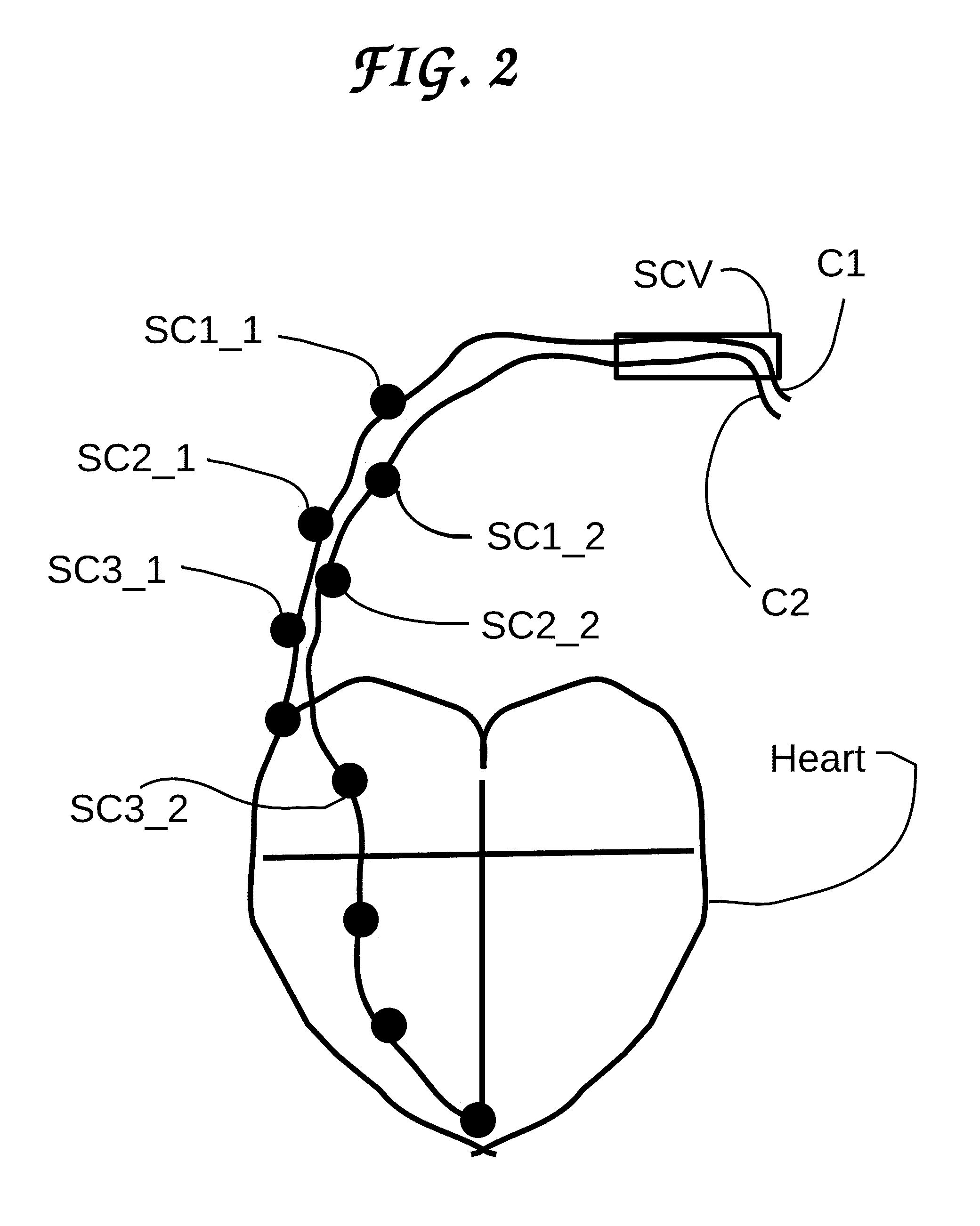
[0060]In the following we are introducing some terms with precisely defined meaning which we clarify here: these are passive electrodes, active electrodes, supercapacitors, picafina, piquita, planarium. Passive electrodes are electrodes which are capable of creating electric field lines, but not capable to inject electric current in the space surrounding them. Physically, and this is most important for this patent, what characterizes an electrode as passive is that it is covered by an electric insulating layer. The insulating layer prevents any electric charge from leaving the electrode to the outside of the supporting structure, whether a picafina, a piquita, a planarium or any other type. The reader should keep in mind that electrical insulators do not prevent the electric field lines from existing past the insulating layer covering the passive electrodes, but only prevent the electric charges from penetrating them, and, consequently, the passive electrodes are perfectly capable o...


PUM


Abstract

An electric stimulator for heart, brain, organs and general cells with a possibly random shape and position of electrodes which enhances its performance for breaking the symmetry. Two types of electrodes are introduced: type-1, or active electrodes are similar to prior art, while type-2, or passive electrodes have not been used in this context. Passive electrodes are electrically insulated, being unable to inject current in the surrounding medium, but they are capable of shaping the electric field, which has consequence on the path of the stimulating currents injected by type-1 electrodes. The invention also discloses a supercapacitor-type passive electrode of type-2, which maximizes the stored charge on the electrode—therefore increasing the electric field magnitude created by it.

Description

CROSS-REFERENCE TO RELATED APPLICATIONS[0001]This application claims priority to U.S. provisional patent application No. 61 / 881,997 dated 25 Sep. 2013, entitled “Cell electric stimulator with electrodes for electrical field shaping and separate electrodes for stimulation” and U.S. provisional patent application No. 62 / 027,116 dated 21 Jul. 2014, entitled “Cell electric stimulator with electrodes for electrical field shaping and separate electrodes for stimulation”, with the same inventors as this patent application.[0002]This application is related to U.S. Provisional Patent Application No. 61 / 486,179 dated 13 May 2011, entitled “Cell electric stimulator with randomized spatial distribution of electrodes for both current injection and for field shaping”, later regular U.S. patent application Ser. No. 13 / 470,275, application date 12 May 2012, published with number US-2012-0289823 A1 on 15 Nov. 2012, currently allowed, and also related to European patent application number EP 2012 016...

Claims


Application Information

Patent Timeline
IPC IPC(8): A61N1/36A61N1/362A61N1/05A61N1/372
CPCA61N1/36185A61N1/37223A61N1/0529A61N1/05A61N1/362A61N1/025A61N1/0534A61N1/0565A61N1/36067A61N1/3686
Inventor LEE, CHONG ILMONTEIRO, SERGIO LARA PEREIRA
Owner LEE CHONG IL
Learn More