Method and apparatus for dehydrating veneer

a technology for dehydrating wood and veneer, applied in lighting and heating apparatus, manufacturing tools, drying machines with progressive movements, etc., can solve the problems of easy over-extension of the elastic-plastic range of the knot, the presence of relatively hard knots in wood veneer, and the breakage of knots into small pieces

Active Publication Date: 2015-05-21
MEINAN MASCH WORKS INC
View PDF16 Cites 7 Cited by
  • Summary
  • Abstract
  • Description
  • Claims
  • Application Information

AI Technical Summary

Benefits of technology

[0009]The second dehydrating rollers of a veneer dehydrating apparatus are disposed with a pace formed between any two adjacent second dehydrating rollers. The veneer dehydrating apparatus may further include a filler member which is fixedly mounted to the support device for each second dehydrating roller at a position between any two adjacent second dehydrating rollers and spaced away from the first dehydrating roller at a distance that is substantially the same as or smaller than the thickness of the veneer sheet. The filler member is configured to fill partially the space between any two adjacent second dehydrating rollers thereby to restrict the flow of water squeezed out from the veneer sheet.
[0010]Method for dehydrating veneer according to the present inv

Problems solved by technology

In dehydrating veneer by compression or squeezing, however, the presence of a relatively hard knot in wood veneer poses a problem.
Therefore, when a veneer sheet having therein any knot is passed between the dehydrating rollers and compressed across the thickness by such rollers, the strain of the knot easily exceeds its elastic-plastic range, with the resul

Method used


Image

  • Method and apparatus for dehydrating veneer
  • Method and apparatus for dehydrating veneer
  • Method and apparatus for dehydrating veneer

Examples


first embodiment

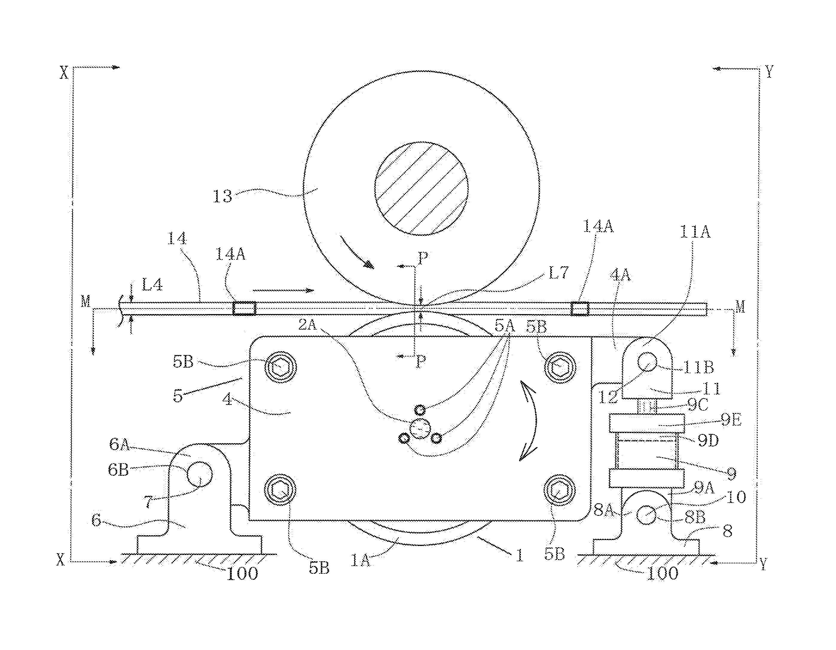
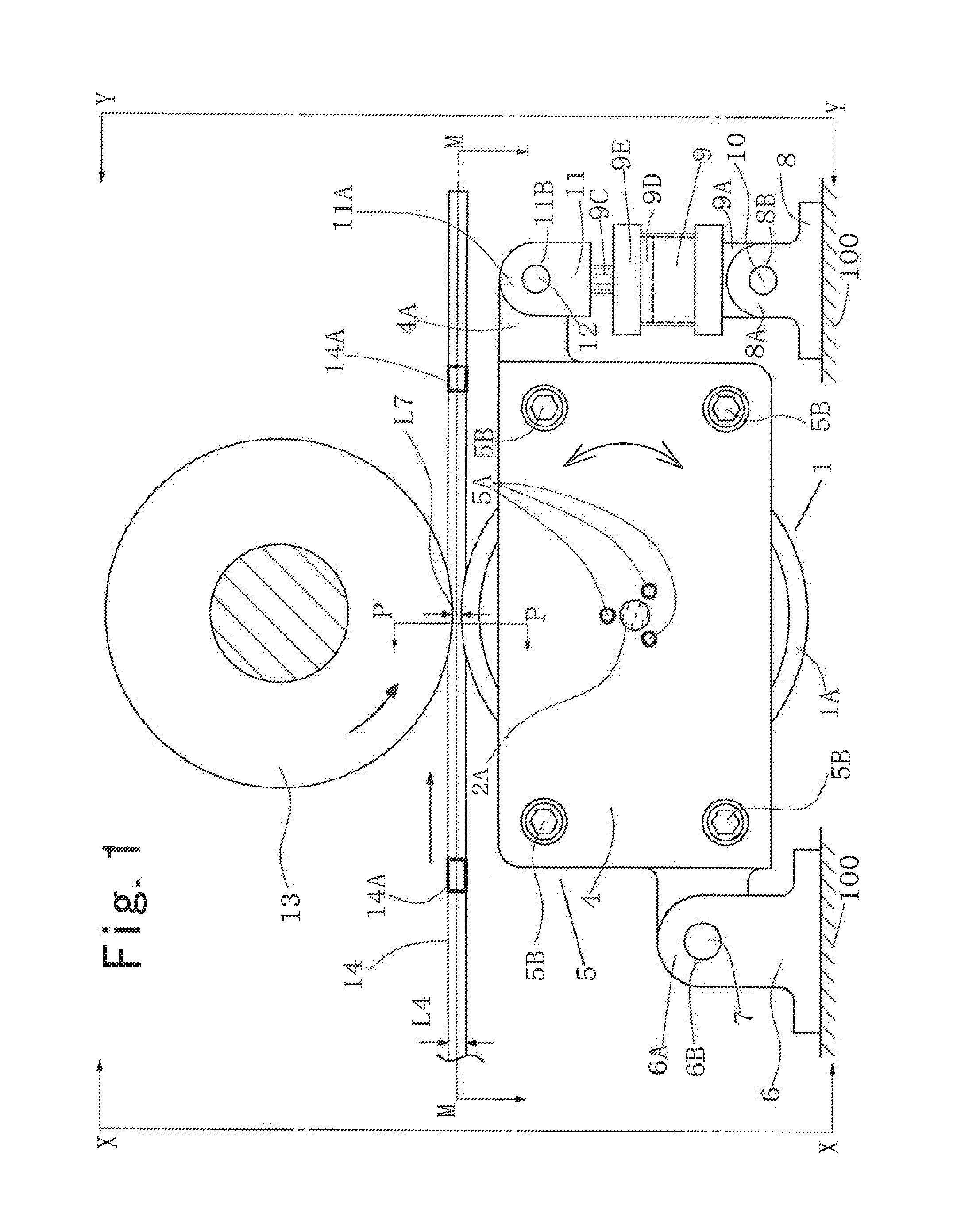
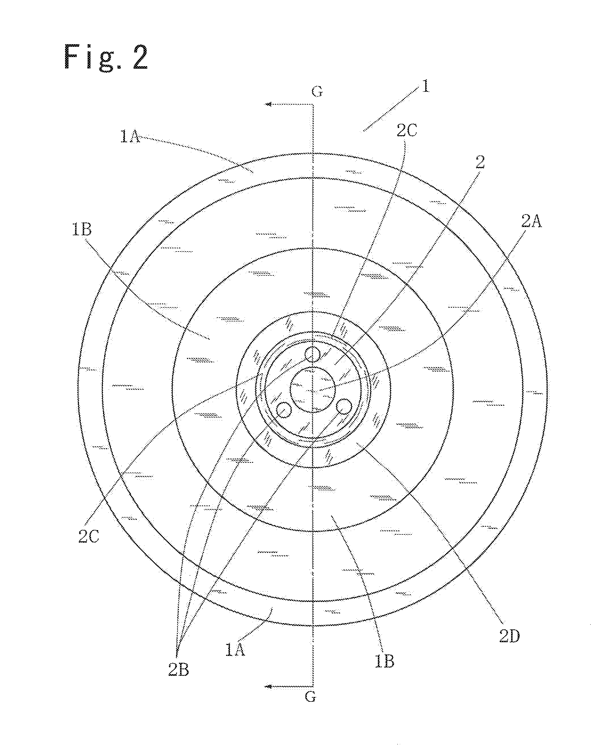
[0046]As shown in FIG. 11, there exist regions of clearance 15 between the rim portions 1A of any two adjacent lower dehydrating rollers 1 where the veneer sheet 14 is clear of contact with the lower dehydrating roller 1. Part of the water squeeze and flowing out from the veneer sheet 14 is attached to the lower surface of the veneer sheet 14 that is exposed to the clearance region 15 and moved past the dehydrating rollers 13, 1 with the veneer sheet 14. Such water is absorbed by the veneer sheet 14 which is then expanded to resume its original thickness after moving past the nip between the upper and the lower dehydrating rollers 13, 1. therefore, the veneer sheet 14 moved past the apparatus may have an irregularity in the degree of dehydration. Such veneer sheet, if kiln dried, will suffer from an irregularity in the moisture content, which may cause insufficient or failure in the lamination of veneer.

[0047]The second embodiment of the present invention shown in FIGS. 12 and 13 h...

third embodiment

[0051]In the third embodiment, the lower dehydrating roller 1 is movable away from the first dehydrating roller 13 by causing the support members 31, 41 to swing about the pivot shaft 30 against the urging force due to the presence of any knot such as 14A moving past the nip between the upper and the lower dehydrating rollers 13, 1.

[0052]In the above first to third embodiments, the diameter of the upper dehydrating roller 13 may be between 200 mm and 500 mm and the width L1 of the rim portion 1A of the lower dehydrating roller 1 between 30 mm to 80 mm.

[0053]The above-described embodiments may be modified in various way without departing from the spirit of the present invention, as exemplified below.

[0054]In the above-described embodiments, the initial setting position of the lower dehydrating roller 1 where the spaced distance L7 is formed between the upper and the lower rollers 13, 1 is accomplished by the contact of the piston 9D with the inner surface of the upper end 9E of the c...


PUM


Abstract

Method and apparatus for dehydration of veneer sheet having therein a knot are disclosed. Veneer dehydration apparatus includes a first stationary single dehydrating roller and a plurality of second movable sectional dehydrating rollers, which rollers are disposed one above the other so that a nip through which a veneer sheet for dehydration is moved is formed between the first and second rollers. A stop device determines the initial position of each second roller relative to the first roller where a predetermined spaced distance is formed between the first and the second rollers. An urging device yieldably urges each second roller to the initial position. The second roller is movable away from the initial position against the urging force of the urging device independently of the other second rollers by a knot present in the veneer sheet and just moving through the nip between the second roller and the first roller.

Description

BACKGROUND OF THE INVENTION[0001]The present invention relates to an apparatus for dehydrating wood veneer or removing water contained in veneer by mechanical squeezing and also to a method therefor.[0002]Wood veneer has been used widely for production of various veneer laminated products such as plywood, laminated veneer lumber (LVL), etc. Multiple layers of veneer are assembled together with an adhesive into the form of a panel, a board or lumber. Prior to the assembling, sheets of green or undried veneer are dried to the desired level of moisture content. As a preparation for such drying, dehydration of veneer or removing part of the water contained in the veneer by mechanical compression or squeezing of the veneer across the thickness thereof has been practiced in some veneer or plywood mills.[0003]A typical veneer dehydrating apparatus is disclosed by U.S. Pat. No. 6,505,658. The veneer dehydrating apparatus has a pair of rotatable dehydrating rollers disposed one above the oth...

Claims


Application Information

Patent Timeline
IPC IPC(8): F26B13/28B30B3/04F26B5/14
CPCF26B13/28B30B3/04F26B5/14B27D1/005B30B9/20F26B2210/14
Inventor NOZAWA, YOSHIOKISAKAMOTO, SHIN-ICHI
Owner MEINAN MASCH WORKS INC
Why Eureka
Try Eureka