Telemetry operated ball release system

a technology of ball release system and telemetry, which is applied in the direction of survey, borehole/well accessories, construction, etc., can solve the problems of inconvenient operation, inconvenient maintenance, and inability to operate,

Active Publication Date: 2015-05-21
WEATHERFORD TECH HLDG LLC
View PDF2 Cites 26 Cited by
  • Summary
  • Abstract
  • Description
  • Claims
  • Application Information

AI Technical Summary

Problems solved by technology

Traditional ball seats, however, suffer from several shortcomings.
First, the shear values required to release the ball from the ball seat can vary greatly, and thus, the ball can inadvertently be released at an undesired pressure.
Secondly, in some instances, hydrostatic pressure volume can be so great that landing of the ball on the seat is never detected.

Method used


Image

  • Telemetry operated ball release system
  • Telemetry operated ball release system
  • Telemetry operated ball release system

Examples


Embodiment Construction

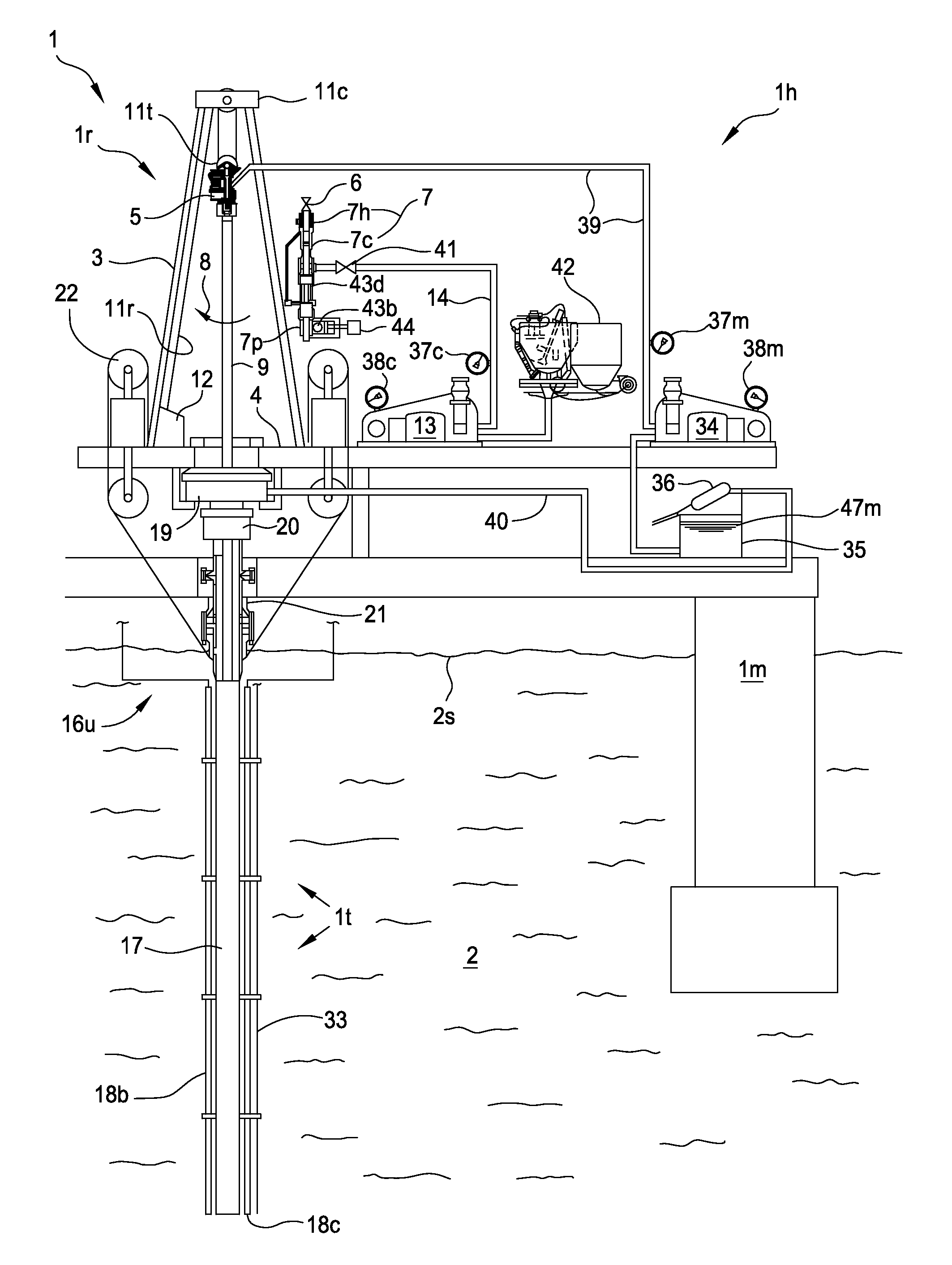
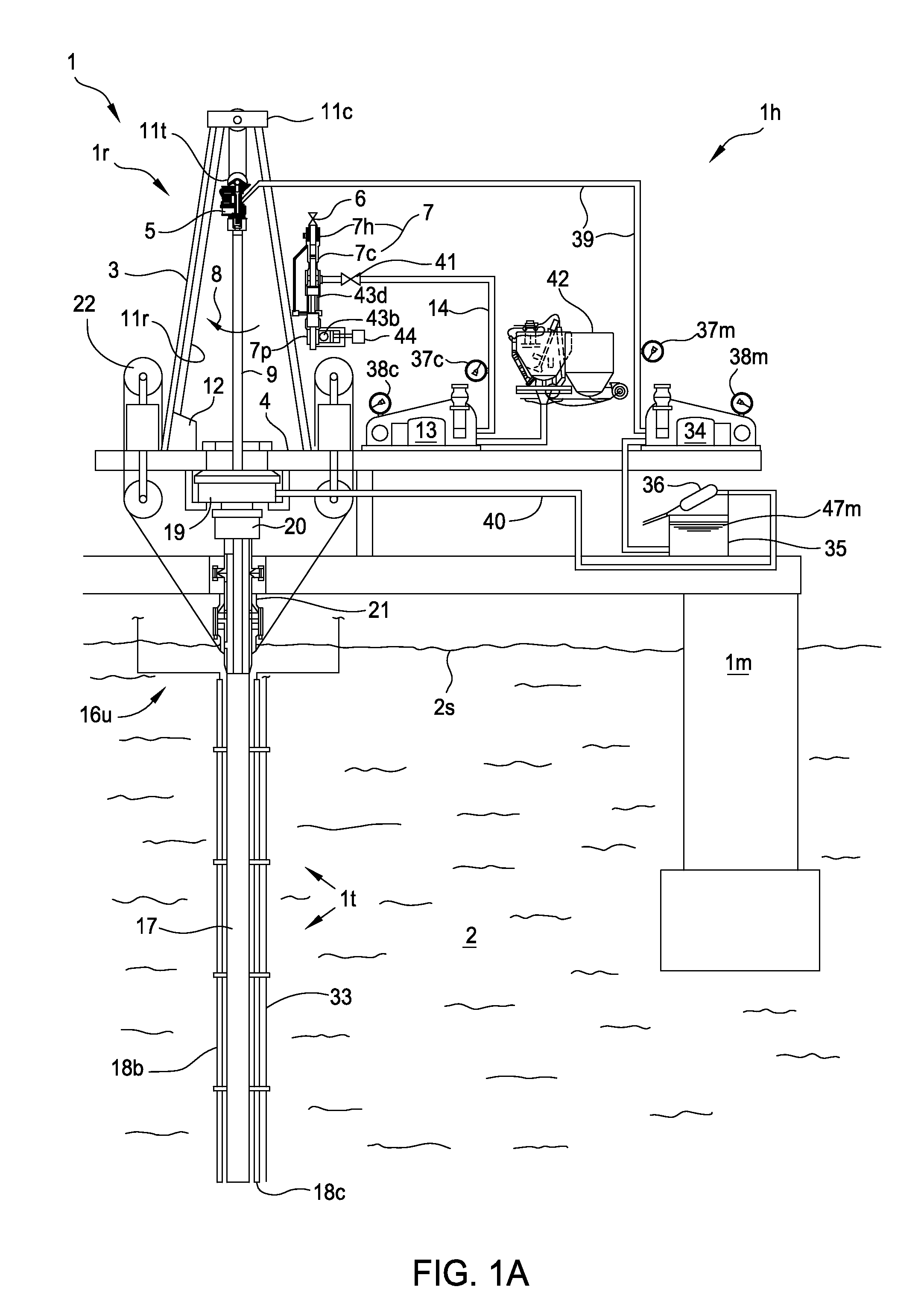
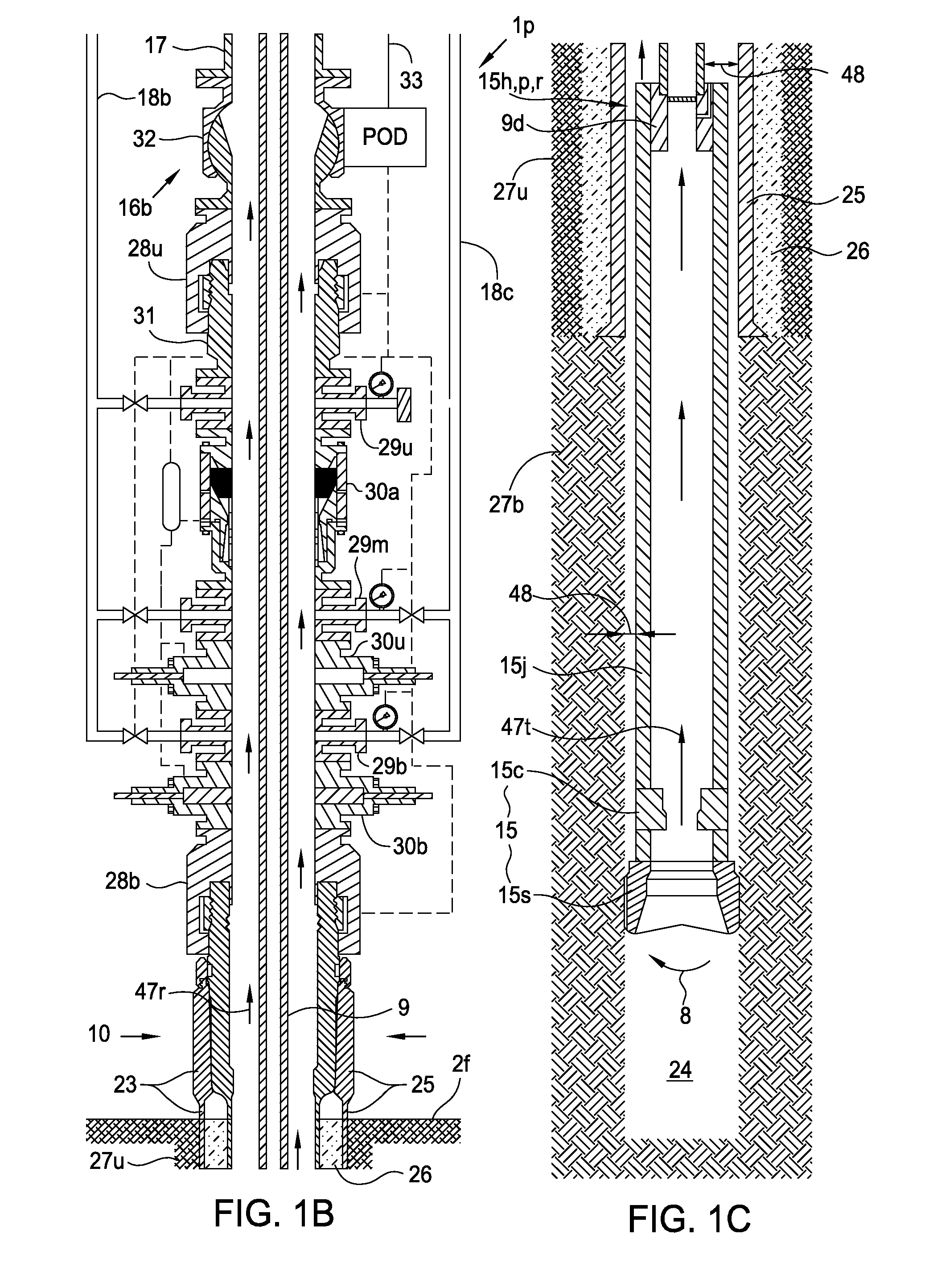
[0016]FIGS. 1A-1C illustrate a drilling system 1 in a liner deployment mode, according to one embodiment of this disclosure. The drilling system 1 may include a mobile offshore drilling unit (MODU) 1m, such as a semi-submersible, a drilling rig 1r, a fluid handling system 1h, a fluid transport system 1t, a pressure control assembly (PCA) 1p, and a workstring 9.

[0017]The MODU 1m may carry the drilling rig 1r and the fluid handling system 1h aboard and may include a moon pool, through which drilling operations are conducted. The semi-submersible MODU 1m may include a lower barge hull which floats below a surface (aka waterline) 2s of sea 2 and is, therefore, less subject to surface wave action. Stability columns (only one shown) may be mounted on the lower barge hull for supporting an upper hull above the waterline 2s. The upper hull may have one or more decks for carrying the drilling rig 1r and fluid handling system 1h. The MODU 1m may further have a dynamic positioning system (DPS)...


PUM


Abstract

In one embodiment, a ball release system for use in a wellbore includes a tubular housing, a seat disposed in the housing and comprising arcuate segments arranged to form a ring, each segment radially movable between a catch position for receiving a ball and a release position, a cam disposed in the housing, longitudinally movable relative thereto, and operable to move the seat segments between the positions, an actuator operable to move the cam, and an electronics package disposed in the housing and in communication with the actuator for operating the actuator in response to receiving a command signal.

Description

BACKGROUND OF THE DISCLOSURE[0001]1. Field of the Disclosure[0002]The present disclosure generally relates to a telemetry operated ball release system.[0003]2. Description of the Related Art[0004]A wellbore is formed to access hydrocarbon bearing formations, e.g. crude oil and / or natural gas, by the use of drilling. Drilling is accomplished by utilizing a drill bit that is mounted on the end of a tubular string, such as a drill string. To drill within the wellbore to a predetermined depth, the drill string is often rotated by a top drive or rotary table on a surface platform or rig, and / or by a downhole motor mounted towards the lower end of the drill string. After drilling to a predetermined depth, the drill string and drill bit are removed and a section of casing is lowered into the wellbore. An annulus is thus formed between the string of casing and the formation. The casing string is cemented into the wellbore by circulating cement into the annulus defined between the outer wall...

Claims


Application Information

Patent Timeline
Patent Type & Authority Applications(United States)
IPC IPC(8): E21B33/16E21B33/10E21B47/12
CPCE21B33/16E21B33/10E21B47/12E21B23/00E21B34/14E21B23/10E21B23/08E21B47/13E21B34/142E21B33/12E21B33/14E21B43/10E21B47/06
Inventor TURLEY, ROCKY A.CAMPBELL, ROBIN L.
Owner WEATHERFORD TECH HLDG LLC
Why Eureka
Try Eureka