
Hydraulically Operated Polished Rod Clamp

Inactive Publication Date: 2015-05-21
NAT OILWELL VARCO LP
View PDF8 Cites 2 Cited by
  • Summary
  • Abstract
  • Description
  • Claims
  • Application Information

AI Technical Summary

Benefits of technology

The patent describes a polished rod clamp that is used to connect a rotary power source to a rod string. The clamp has a wedge lock that can grip the rod and apply force in opposite directions to move it. The clamp is housed in a cavity and has a piston that applies force to the wedge lock to move it. The patent also describes a drive system that includes the clamp and a rod pump driver, which can be a rotary or axially reciprocating pump. The system includes a mount that aligns the central passage of the clamp with the central bore of the drive shaft, and hydraulic pressure is applied to the clamp to move the wedge lock and grip the rod string. The technical effects of the invention include improved coupling of a rotary power source to a rod string, simplified design and operation, and improved reliability and efficiency of the drive system.

Problems solved by technology

Applying such high torque with a conventional wrench from the top of an elevating device, such as a step ladder, can be dangerous.

Method used


Image

  • Hydraulically Operated Polished Rod Clamp
  • Hydraulically Operated Polished Rod Clamp
  • Hydraulically Operated Polished Rod Clamp

Examples


Embodiment Construction

[0019]In the following detailed description, numerous specific details may be set forth in order to provide a thorough understanding of disclosed embodiments. However, it will be clear to one skilled in the art when embodiments disclosed herein may be practiced without some or all of these specific details. In other instances, well-known features or processes may not be described in detail in the disclosed embodiments so as not to unnecessarily obscure the disclosure. In addition, like or identical reference numerals may be used to identify common or similar elements.

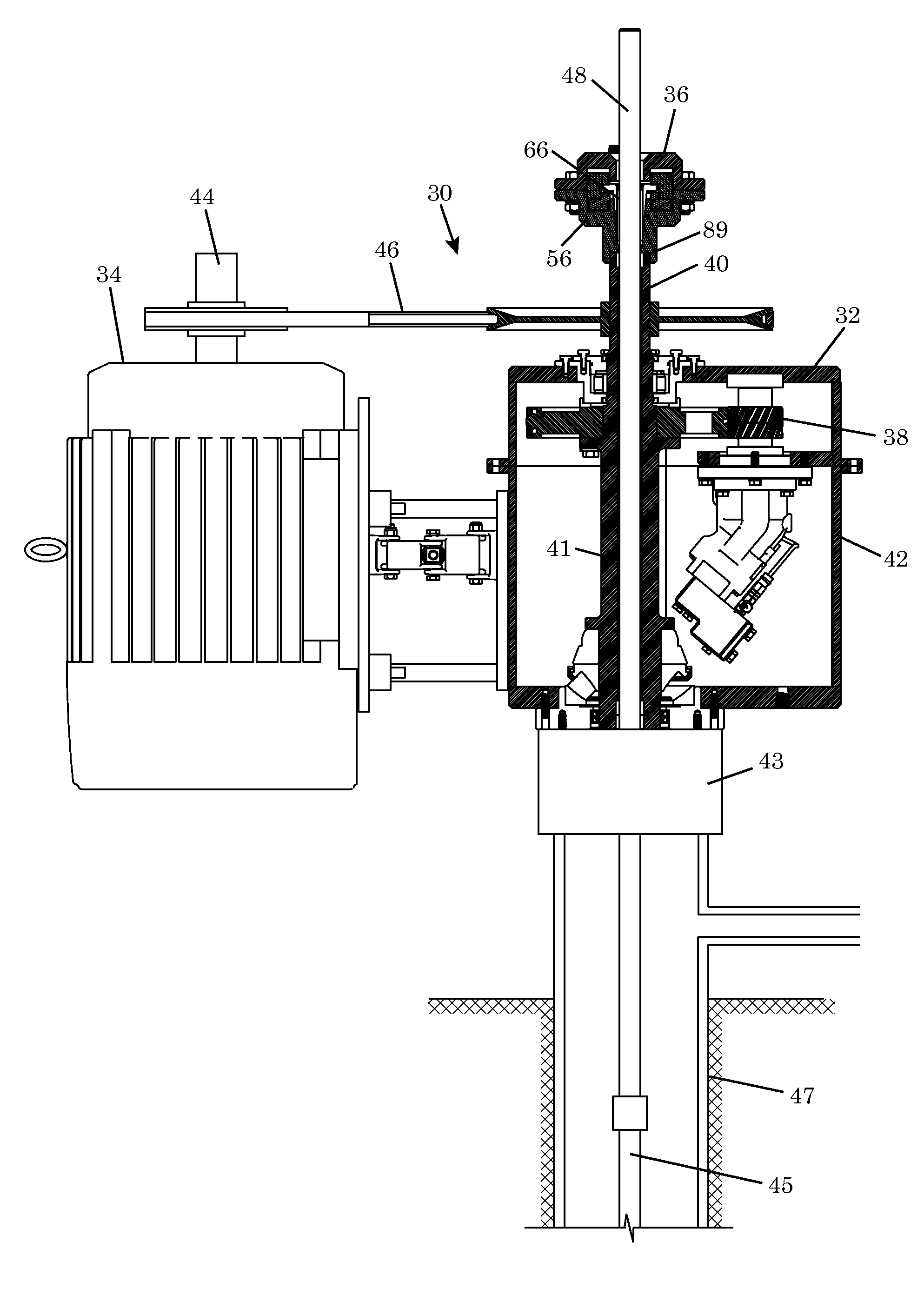
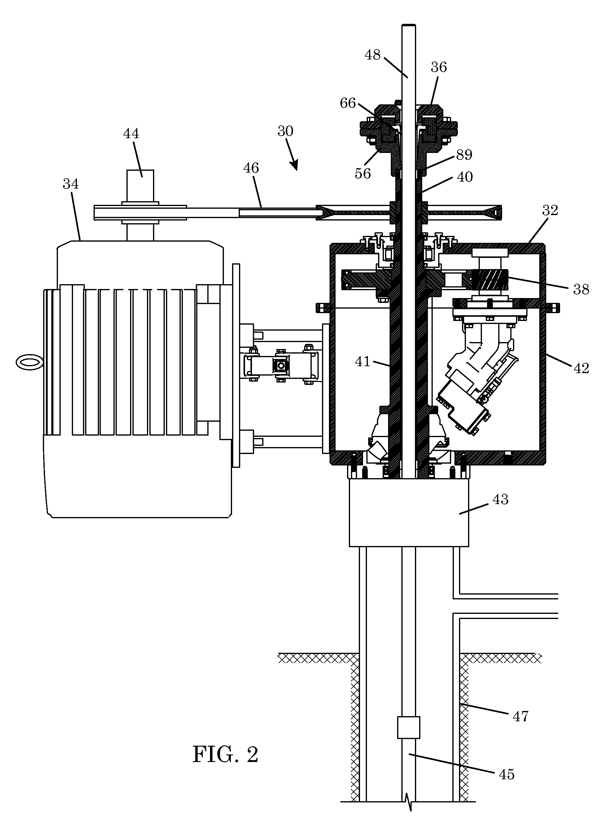
[0020]FIG. 2 shows an illustrative embodiment of a rotary drive 30 including a drive head 32 and a driver or motor 34. The drive head 32 includes a gear box 38, which is coupled to a drive shaft 40. The drive shaft 40 extends out of the drive head housing 42 and is coupled to an output shaft 44 of the motor 34 by a belt drive 46. The motor 34, belt drive 46, and gear box 38 rotate the drive shaft 40 with a desired torqu...


PUM


Abstract

A polished rod clamp includes a clamp housing having a central passage passing through a tapered bore. A wedge lock is arranged in the tapered bore such that a first surface of the wedge lock is in sliding engagement with a tapered surface of the tapered bore and a second surface of the wedge lock grips a rod in the central passage in a lock position. A first reciprocating piston is arranged to apply a first force to the wedge lock that effects a relative sliding motion between the wedge lock and the tapered surface in a first direction corresponding to the lock direction of the wedge lock. A second reciprocating piston is arranged to apply a second force to the wedge lock that effects a relative sliding motion between the wedge lock and the tapered surface in a second direction that is opposite to the first direction.

Description

CROSS-REFERENCE TO RELATED APPLICATIONS[0001]Not applicable.STATEMENT REGARDING FEDERALLY SPONSORED RESEARCH OR DEVELOPMENT[0002]Not applicable.BACKGROUND[0003]The present disclosure relates generally to a mechanism for coupling a power source to a rod string, such as a sucker rod string.[0004]A string of sucker rods is used to couple a rod pump in a well with a reciprocating or rotary power source at the surface. The uppermost joint in the sucker rod string is known as a polished rod (or polish rod). The polished rod is machined to a high diametrical tolerance and has a polished external surface that enables a hydraulic seal to be made around the sucker rod string as the sucker rod string reciprocates or rotates. The polished rod passes through a wellhead stuffing box, which establishes a seal against the polished rod. Typically, a polished rod clamp is used to couple the polished rod to the surface power source, which may be a walking beam in the case of a reciprocating pump syste...

Claims


Application Information

Patent Timeline
IPC IPC(8): E21B17/03
CPCE21B17/03E21B43/126E21B19/12
Inventor WHITE, BILL W.
Owner NAT OILWELL VARCO LP
Learn More