Thin push button structure

Active Publication Date: 2015-05-21
ICHIA TECH
View PDF11 Cites 19 Cited by
  • Summary
  • Abstract
  • Description
  • Claims
  • Application Information

AI Technical Summary

Benefits of technology

[0008]The instant disclosure provides a thin push button structure to reduce the thickness of the key. In addit

Problems solved by technology

However, some issues remained to be solved before achieving even thinner push button structure.
More specifically, when a user does not presses the central region of the key, the k

Method used


Image

  • Thin push button structure
  • Thin push button structure
  • Thin push button structure

Examples


first embodiment

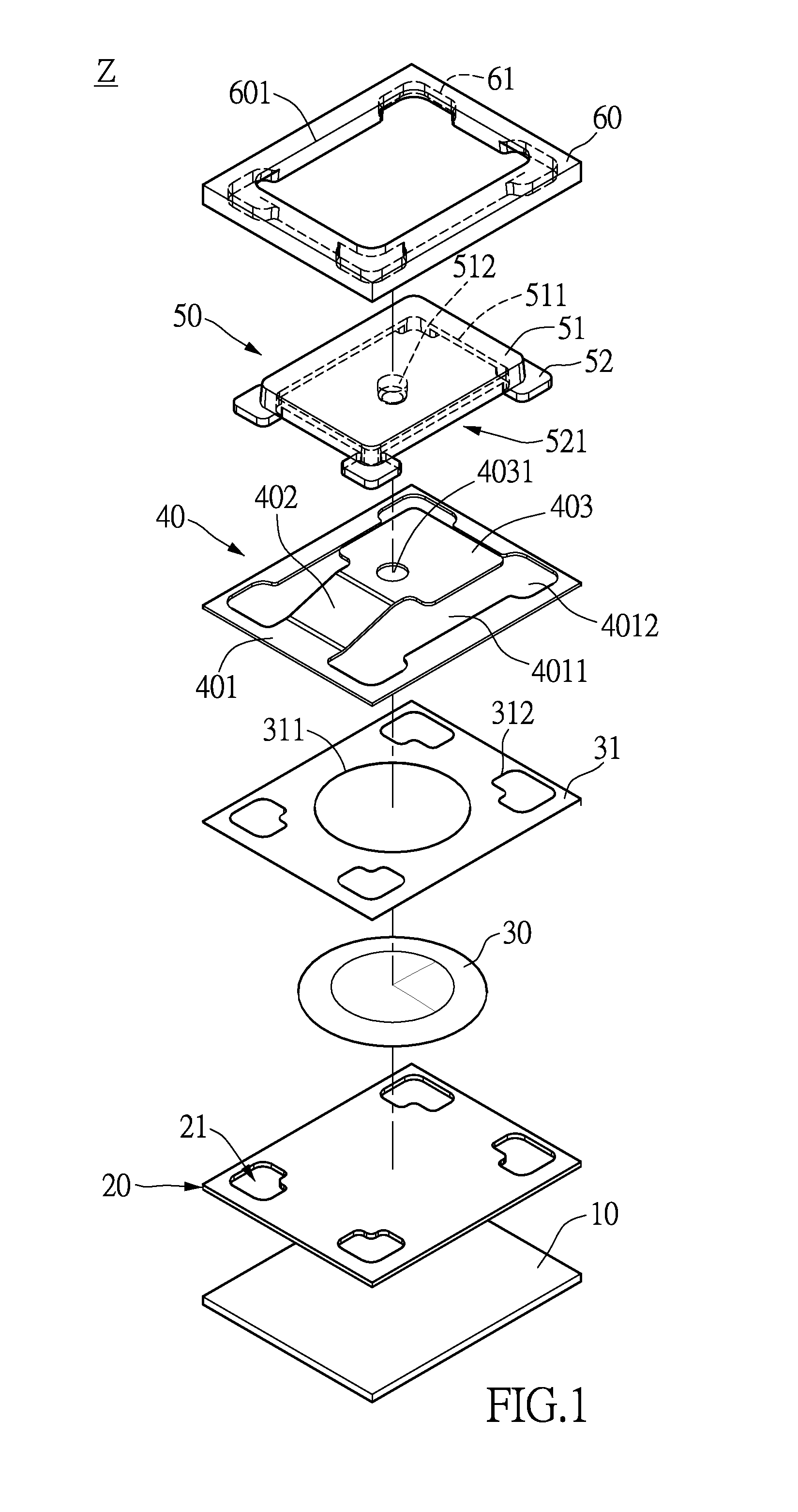
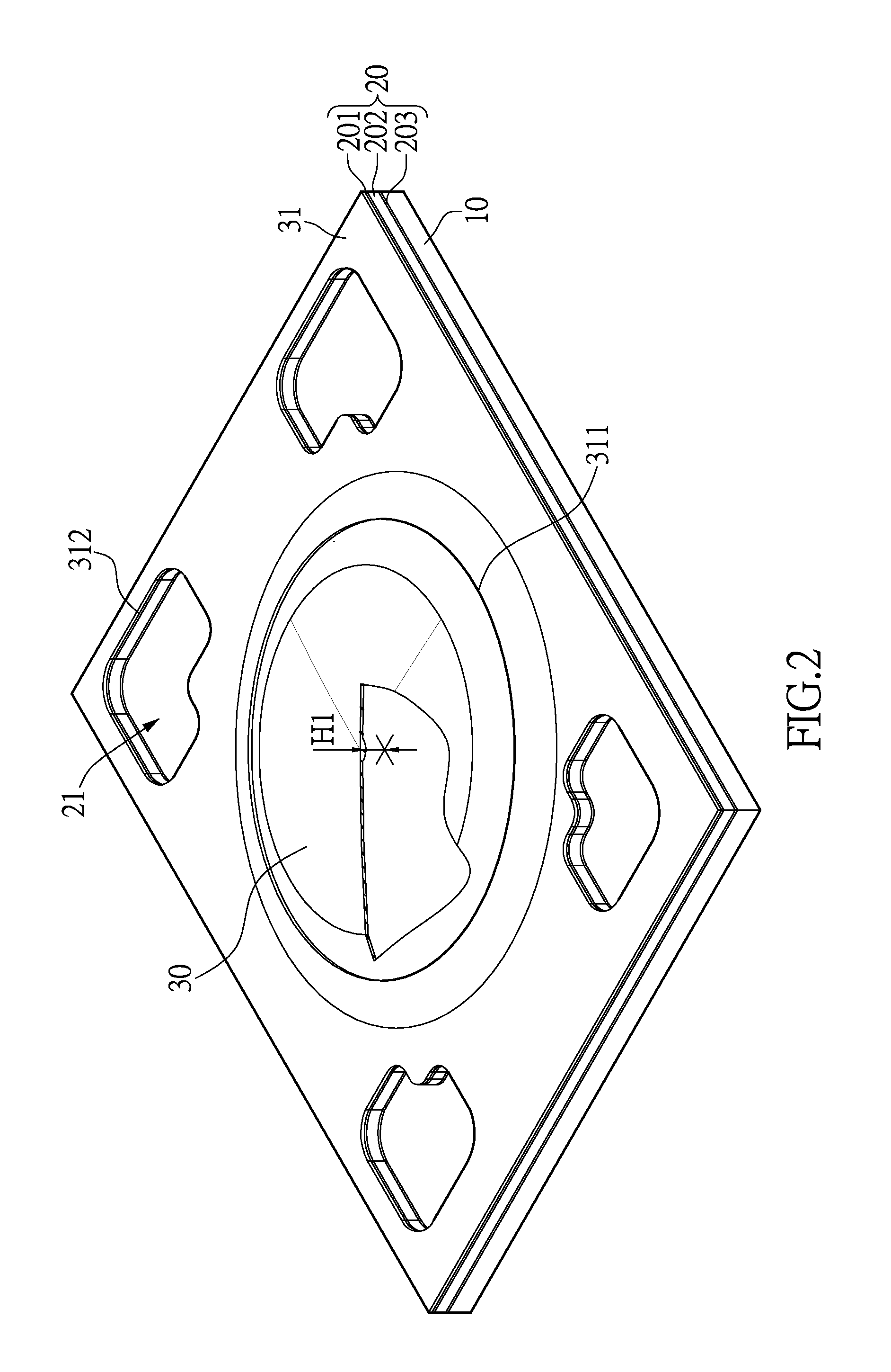
[0033]Please refer to FIGS. 1 to 9. FIG. 1 is an exploded view of a thin push button structure in accordance with the instant disclosure. FIGS. 2 to 8 are diagrams showing elements of the thin push button structure. FIG. 9 is a diagram showing the thin push button structure. As shown in FIG. 1, the thin push button structure includes a main board 10, a circuit board 20, an elastic element (a movable contact) 30, a supporting plate 40, a key top 50 and a frame 60. The circuit board 20, elastic element 30, supporting plate 40, key top 50 and frame 60 are disposed in succession on the main board 10. Preferably, the main board 10 is made of aluminum. The circuit board 20 may be a circuit membrane, flexible printed circuit (FPC) or flexible flat cable (FFC). The elastic element 30 may be a metal dome. The supporting plate 40 may be made of hard yet deformable membrane. The supporting plate 40 may be made of, for example, polycarbonate (PC), polyethylene terephthalate (PET), thermoplastic...

second embodiment

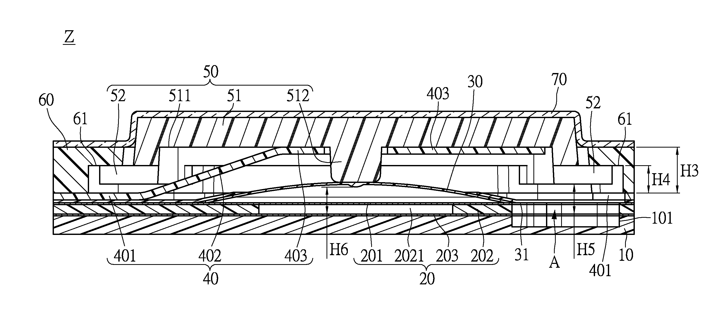
[0039]Please refer to FIGS. 10 to 12, which show the movement when a user presses the central region of the thin push button structure Z. FIG. 10 shows a cross-sectional view before the key top 50 is pressed. In the instant embodiment, the circuit board 20 has three layers including the top layer, a first conductive layer 201, a spacer 202 and the last layer, a second conductive layer 203. The first and second conductive layers 201, 203 have opposite electrode polarities. The spacer 202 is formed with a conduction hole 2021 at its central region. The dome of the elastic element 30 is positioned to the conduction hole 2021 of the spacer 202, and the stem 512 of the main body 51 aims at the dome of the elastic element 30. After the main body 51 covers the contacting portion 403 of the supporting plate 40, the stem 512 of the main body 51 contacts the dome apex of the elastic element 30.

[0040]As shown in FIG. 10, the distance H3 from the contacting portion 403 to the seat 401 is longer...

third embodiment

[0042]FIGS. 13 to 16 show the movement when the key top 50 is pressed at the peripheral region. When a user presses a corner of the key top 50, the post 52 of the opposite corner (for example, the diagonal corner) is brought up and abuts the alignment groove 61 of the frame 60. As a result, the post 52, which abuts the alignment groove 61, becomes a fulcrum. The key top 50 pivots by taking the vary post 52 as a fulcrum. Then the tilted key top 50 abuts the elastic element 30 through the stem 512. Subsequently the first and second conductive layers 201, 203 of the circuit board 20 are electrically conducted, and the signal is generated.


PUM


Abstract

A thin push button structure includes a main board, a circuit board, an elastic element, a supporting plate, a key top and a frame. The circuit board is disposed on the main board and formed with a plurality of cavities. The supporting plate includes a seat, an extending portion and a contacting portion. The seat is formed with a window at the central region and connected to the contacting portion by the extending portion. The elastic element is disposed on the circuit board. The key top includes a main body and a plurality of posts that extend therefrom. The frame includes a through opening and a plurality of alignment grooves at the periphery of the opening. The frame sleeves the key top, and the posts are received by the alignment grooves. The key top caps the contacting portion and is movable within the alignment grooves and the cavities.

Description

BACKGROUND[0001]1. Field of the Invention[0002]The instant disclosure relates to a push button structure, in particular, to a thin push button switch.[0003]2. Description of Related Art[0004]Push button structure is a common input device. The push button is widely used in different electronic products, for example, mobile phone, iPad and remote control. As electronic devices become thinner, the push button structure has to reduce its thickness as well. However, some issues remained to be solved before achieving even thinner push button structure.[0005]For example, a conventional push button structure includes a key, a movable layer and a circuit board. The movable layer is disposed underneath the key and on top of the circuit board. The movable layer has flexible plates disposed at a position corresponding to the key. When the key is pressed, the flexible plate is pressed, and the central region of the flexible plate forms a dimple. Then a contact point on the circuit board is touch...

Claims


Application Information

Patent Timeline
IPC IPC(8): H01H13/10H01H13/06H01H13/04
CPCH01H13/10H01H13/04H01H2223/002H01H2237/006H01H2227/036H01H13/06H01H13/52H01H13/86H01H2013/525H01H2217/01
Inventor LIU, CHANG -LICHANG, YU- CHIH
Owner ICHIA TECH
Why Eureka
Try Eureka